
L293 Basic Bipolar Stepper Motor Driver Configuration Circuit

The circuit employs either the L293 or L298N integrated circuit, both of which are designed for driving motors and can handle bi-directional control of the stepper motor phases. The bipolar stepper motor consists of two coils that need to be energized in a specific sequence to achieve rotation. The L293 and L298N drivers facilitate this by providing the necessary current and voltage levels to the motor coils.
In this configuration, the control signals are typically generated by a microcontroller, which sends pulse-width modulation (PWM) signals to the driver IC. The driver IC interprets these signals and activates the appropriate outputs to energize the motor coils in the correct order. This is crucial for creating the magnetic fields that cause the motor to step forward or backward.
The L293 driver can handle up to 600 mA per channel, making it suitable for smaller stepper motors, while the L298N can handle up to 2 A per channel, allowing it to drive larger motors. Both devices include built-in diodes for flyback protection, which is essential for preventing voltage spikes generated by the inductive loads of the motor coils from damaging the driver circuitry.
For optimal performance, it is important to ensure that the power supply voltage is within the specifications of the chosen driver and motor. Additionally, proper heat dissipation measures should be implemented, especially when using the L298N, as it can generate significant heat during operation.
Overall, this circuit configuration provides a straightforward and effective means of controlling a bipolar stepper motor, suitable for various applications in robotics, automation, and other fields requiring precise motor control.The herein circuit shows basic configuration for bipolar stepper motor driving which can be applied using either an L293 or an L298N. This circuit shows that a single device can be used to drive a two phase bipolar stepper motor 🔗 External reference
Related Circuits
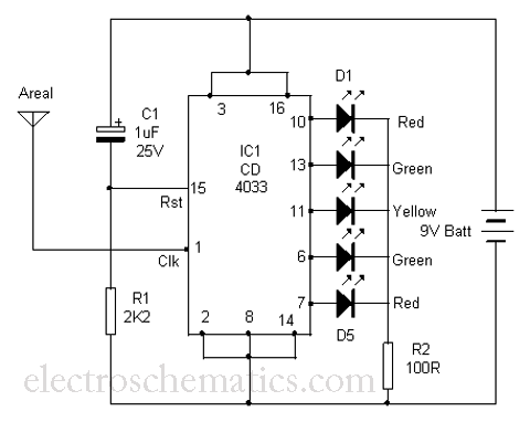
This is a simple tool designed to measure the level of radiation emitted by electrical or electronic devices. The circuit utilizes LEDs to create a running light pattern when it detects electromagnetic radiation from a source. It can detect...
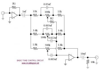
The following diagram illustrates the schematic of an Active Tone Control circuit, commonly referred to as "ACTOR." The ACTOR is an electronic audio circuit designed to enhance loudness by adjusting bass and treble audio signals. It operates using the...
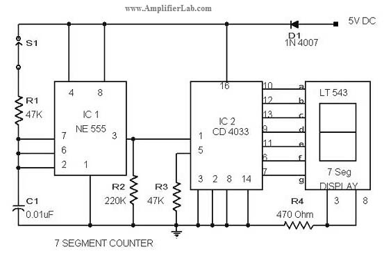
The circuit diagram of a 7-segment counter circuit has been published here. This circuit consists of the counter IC CD4033 as its central component. The 7-segment counter circuit utilizing the CD4033 integrated circuit (IC) is designed to display decimal digits...

Digital Command Control (DCC) provides significant advantages over traditional DC analog control systems, primarily due to its simplified wiring. DCC enables the individual control of multiple locomotives on the layout without requiring electrical isolation of track sections. The main...
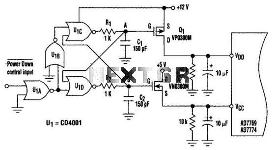
This circuit adds a power-down function to analog I/O ports, such as the AD7769 and AD7774. Additionally, the diodes typically required to protect the devices against power-supply mis-sequencing can be eliminated. In this design, MOSFETs Q1 and Q2 switch...
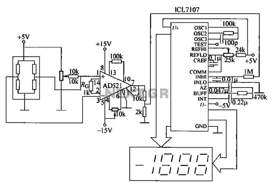
A pressure sensor circuit features a pressure sensor with a nominal resistance of 120 ohms. The amplifier circuit utilizes an AD521 operational amplifier with a gain of 100. It includes resistor components Rs and Rc, along with a decision-making...