
Dual phone line auto recorder

In the practice was proved that changing the value of R1-13 in 4K7 and R2-14 in 27K is covered a big region of sensitivity in telephone lines. Also were suppressed D1-6 diodes and they were replaced with the bridges BR1-2 that ensures adaptation in any polarity of telephone line.
ATTENTION!!! In a lot of regions exists legislation that prohibits the recording of telephone discussions or the placement of other appliances, except the telephone appliances, in the existing telephone lines. I would request is taken into consideration this legislation front becomes the making the circuit. Also the telephone line 48V are considered low voltage, nevertheless however under certain conditions can become dangerously.
The circuit described enables simultaneous recording from two telephone lines through a tape recorder. The operation of the circuit is initiated when the earphone from either telephone unit is lifted, which activates the recording process. The circuit is designed to supply the necessary voltage to the tape recorder, typically +3V DC, while also allowing the recording to continue if one of the earphones remains lifted. It is crucial that the power supply provides at least +16V DC to ensure proper functionality.
The circuit utilizes an LM7812 voltage regulator (IC4) to supply +12V to the relays, while an LM317T (IC5) is employed to regulate the voltage for the tape recorder. The design incorporates resistors R17 and R18 to limit the input voltage to IC5, minimizing heat generation. Additionally, the circuit features isolation switches (S1 and S2) that can disconnect the circuit from the telephone lines to prevent accidental activation.
Optical isolation is achieved through optocouplers (IC1-3), which work in conjunction with a 4011 NAND gate (IC2) to control the relays (RL1-2). These relays manage the power supply to the tape recorder, ensuring that recording only occurs when the circuit is activated. Capacitors (C1-6) are included to filter out ringing pulses, preventing false triggers during incoming calls.
LEDs (D4-9) provide visual indicators for the active telephone lines, enhancing user awareness. The circuit also includes telephone isolation transformers (T1-2) to ensure that audio signals are appropriately coupled to the tape recorder's input while maintaining electrical isolation.
The component values are adaptable, with specific recommendations for resistors R1-13 and R2-14 to optimize sensitivity across various telephone lines. The inclusion of bridge rectifiers (BR1-2) allows for correct polarity connections, further enhancing the circuit's versatility.
Compliance with local legislation regarding telephone recording is essential, as unauthorized recording may lead to legal repercussions. Additionally, safety precautions should be taken when handling low-voltage telephone lines, as they can pose risks under certain conditions.Many times exists the need recording some conversations from a telephone line and this it's relatively easy. If we want however to have the possibility recording from two telephone lines simultaneously in a tape recorder, we needed a circuit as what appears in the Fig.1.
The circuit stimulates when earphone from a telephone unit is raised, beginning simultaneously and the recording, from the one or from two telephone lines. At the same time it gives the voltage that needs the tape recorder it work also him it stops as we lower also the two earphones.
If somebody of the earphones is raised, then recording is continued regularly. The power supply of circuit can become from external power pack, that will have the possibility to give at least + 16V DC in his output. The IC4 supply the circuit and relay with + 12V and the IC5 with the TR1 can be regulated so as to it gives in the exit his essential voltage that the tape recorder needs to works, usually + 3V DC. The IC4 should be placed on heatsink. The two resistors R17-18 are essential so that they throw the voltage in the input of IC5 in lower levels, so that it's produced as long as the possible least heat than the IC5.
Their value can change so that it matching in your data. The input and output for the telephone lines becomes from the connectors J1-2, follows two switches S1-2 with which we have the possibility is isolated the circuit from the lines, so that we do not have excitation of circuit each time where we will raise the earphone of telephone unit. It can they are suppressed if it's judged that them you don't need. The circuit round the optical optocoupler IC1-3 ensures the isolation of lines from the remainder circuit and in collaboration with the IC2 drive the two relay RL1-2, which the contacts give the supply voltage command in the tape recorder, of also recording.
If the supply of tape recorder becomes from batteries and exist input ''Remote in'', then we can modify the circuit as appear in the Fig.2. Capacitors C1-6 prevents the circuit stimulate when in the line they exist the ringing pulses. The diodes led D4-9 give an optical clue if and who line has turn on. The sound of telephones from the telephone isolation transformers T1-2 and the contacts the relays RL1-2, in by suitable adaptation, drive to the Rec.
input of tape. The typical value for diodes zener D2-7 * is 20V and is in effect for networks with voltage, bigger than + 48V, but it can it changes so that is adapted the circuit in the voltage that exist in your telephone line. [In the practice was proved that changing the value of R1-13 in 4K7 and R2-14 in 27K is covered a big region of sensitivity in telephone lines.
Also were suppressed D1-6 diodes and they were replaced with the bridges BR1-2 that ensures adaptation in any polarity of telephone line]. ATTENTION!!! In a lot of regions exists legislation that prohibits the recording of telephone discussions or the placement of other appliances, except the telephone appliances, in the existing telephone lines.
I would request is taken into consideration this legislation front becomes the making the circuit. Also the telephone line 48V are considered low voltage, nevertheless however under certain conditions can become dangerously. Part List R1-13=4.7Kohm C7-8-11-13=100nF 100V MKT 5% D2-7=20V 1W zener *[see text] R2-14=27Kohm C9=470uF 25V D3-5-8-10=1N4148 R3-15=1Kohm C10=47uF 25V D4-9=LED RED 3mm R4-6-7-10-11-16=10Kohm TR1=4.7Kohm trimmer Q1-2=BD679 R5-9-19=220ohm C12-14=10uF 25V T1-2=TEL.
TRANSFORMER 600R/2X300R R12=68Kohm IC1-3=4N28 [optocupler] RL1-2=12V RELAY R17-18=1.2ohm 5W [see text] IC2=4011 J1-2=4pin connector with 2.54mm step C1-6=10uF 25V IC4=LM7812 J3-4=2pin connector with 2.54mm step C2-3=470nF 250V MKT 5% IC5=LM317T S1-2=Mini Switch 2X2 C4=820pF 100V ceramic BR1-2=BRIDGE RECT. > 1A S3=Mini Switch 1X2 C5=680nF 100V MKT 5% D1-6= -------- 🔗 External reference
Related Circuits
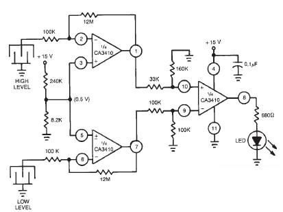
This liquid level sensor electronic circuit diagram utilizes a common CA3410 operational amplifier integrated circuit (IC). The sensor employs two plate sensors (or probes), one designated for detecting high liquid levels and the other for low liquid levels. If...
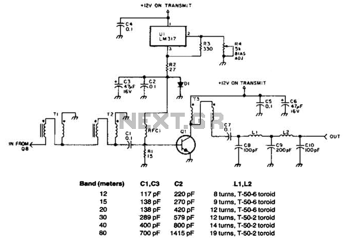
This linear amplifier provides a 10-W PEP output with a 1.25-W drive on the 10 m band. The transformers, T1, T2, and T3, consist of 10 turns of bifilar windings on an FT-50-43 toroidal core and are designed for...
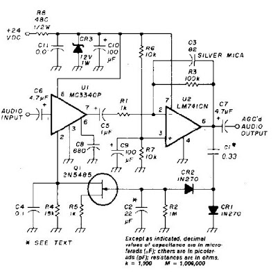
An audio signal applied to VI is passed through the operational amplifier 741, U2. After being amplified, the output signal V2 is sampled and applied to a negative voltage doubler/rectifier circuit composed of diodes CR1 and CR2, along with...
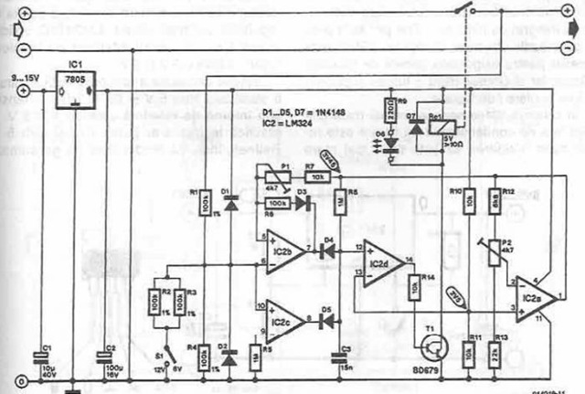
A simple battery charger is designed to disconnect the battery when the charge voltage reaches its nominal level and reconnect when the battery voltage drops below a predefined threshold. This is achieved using a circuit diagram that incorporates a...
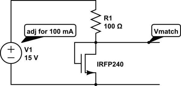
The unit is designed to drive an 80V/10A motor. The current matching circuit is utilized, but there is uncertainty regarding the appropriateness of the MOSFET selection for this application. The circuit for driving an 80V/10A motor typically requires careful consideration...
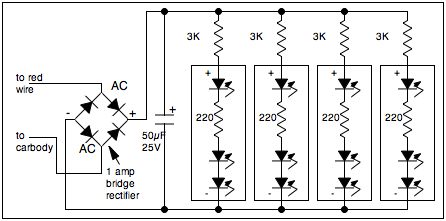
The streamliner passenger car was introduced just before World War II as part of dedicated passenger car and locomotive sets. These cars were designed to be lightweight, enabling high speeds with a relatively small diesel engine. Over time, railroads...