
autoconnect disconnect battery charger

The described battery charger circuit operates on the principle of voltage monitoring and relay control. The voltage divider formed by resistors R1, R2, R3, and R4 allows for a scaled-down representation of the battery voltage, which is critical for ensuring accurate charging control. The operational amplifier (AO) serves as a comparator, assessing the voltage derived from the divider against a reference voltage. The output from the AO determines the state of the relay, which functions as the switching mechanism to connect or disconnect the battery from the charging circuit.
In the charging phase, when the battery is connected, the low voltage across the battery allows for the activation of the relay through the control circuit involving IC2c and associated diodes. The reverse biasing of diodes D4 and D5 prevents current from flowing in the wrong direction, ensuring that the charging path is correctly established. As the battery charges, the voltage rises, and once it reaches the predefined nominal voltage, the operational amplifier output switches, deactivating the relay and cutting off the charging current to prevent overcharging.
Calibration is a crucial aspect of this circuit, allowing the user to set the correct voltage levels for operation. The use of a voltmeter to measure the output of IC2a ensures that the system can be accurately adjusted to the desired voltage levels. The adjustments via potentiometers P1 and P2 allow for fine-tuning, ensuring that the charging process is both efficient and safe.
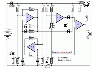
Overall, this circuit provides a reliable and straightforward solution for battery charging, incorporating essential features such as automatic disconnection and reconnection based on battery voltage levels, thereby enhancing battery longevity and performance. The design can be further modified to accommodate different battery types by adjusting the reference voltage and calibration settings accordingly.A simple battery charger that disconnects the battery when charge voltage reaches its nominal voltage and reconnects when battery voltage falls below a predefined level, can be designed using this circuit diagram. A fraction of the battery voltage is taken from the voltage divider R1-R2-R3-R4 and compare with a reference voltage with the help of I
C2b. As long as the battery voltage is 0 V. The input current of AO produces a small voltage drop on R5, so IC2c pass in 0 ³. Therefore, the relay remains disengaged. When connecting a battery, low residual voltage provide switch of IC2c, diodes D4 and D5 are reverse biased, a voltage reference applied to the noninverting input of IC2d and relay is activated. In these conditions, the battery charge until its voltage reaches the nominal level. Calibration is performed with a voltmeter connected to the output of IC2a, then P2 is adjusted, to obtain an indication of 3.
45 V. Further, P1 rotates in the direction of maximum resistance. Replace battery with a stabilized power supply and set output voltage at 6V (6V position S1) or 12V (S1 in position 12 V), which is the voltage when charge is interrupted and adjust P1 until the relay works. 🔗 External reference
Related Circuits
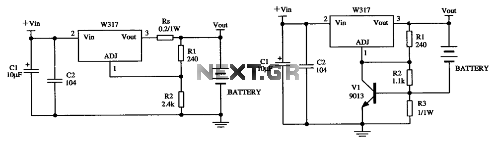
The W317 circuit integrates a three-terminal adjustable voltage regulator designed for battery charging applications. It features a constant pressure limiting charger circuit, where resistor Rs is employed to restrict the charge current, thereby reducing the initial charge rate. Additionally,...
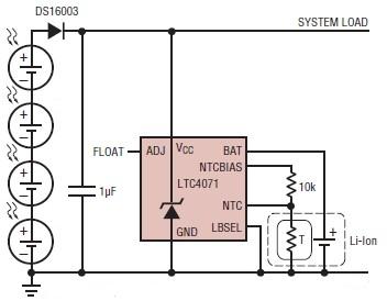
A simple solar-powered battery charger circuit can be designed using the LTC4071 Li-Ion/Polymer Shunt Battery Charger System with Low Battery Disconnect. When VCC reaches the programmed float voltage (4.1V with ADJ floating), the LTC4071 shunts excess current not used...
A motorcycle or boat battery that is not needed during the winter is typically charged before being stored, remaining unused for several months. This inactivity can lead to the accumulation of lead sludge, which may reduce the battery's capacity...
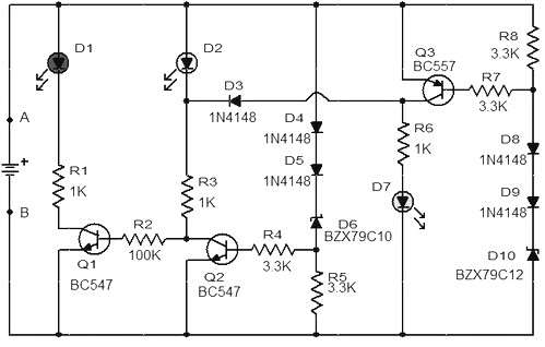
When the battery voltage is 11.5V or less, transistor Q1 is activated, and LED D1 will illuminate. When the battery voltage is between 11.5V and 13.5V, transistor Q2 is activated, causing LED D2 to light up. At a battery...

When USB power is present and the device needs to operate, VSupply is supplied directly by the USB, while a PMOS transistor isolates the battery from the supply. Resistor R3 ensures that the PMOS remains on when USB power...
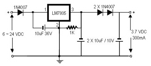
A regulator circuit is needed for this DIY project. Familiarity with electronic components, circuitry, the use of a multitester, and a soldering iron is essential. The schematic diagram provided can accept an input voltage ranging from 6 to 24...