
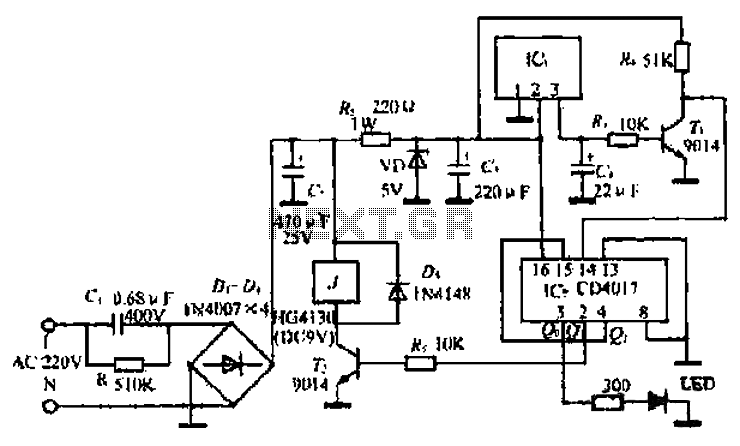
Dual power switch circuit diagram consisting of a single control button CD4069

The circuit utilizes a single push-button switch to manage the operation of two relays, allowing for a simple yet effective means of controlling multiple loads. The hex inverter, specifically the CD4049, serves as the core logic component, converting the momentary push of the button into a toggling action that alternates the state of each relay.
Upon pressing the button, the output from the hex inverter changes state, activating the first relay. This relay, being self-locking, remains engaged until the button is pressed again, at which point the inverter toggles its output and deactivates the relay. The second relay operates in a similar fashion, allowing for independent control of two separate loads or circuits.
The use of self-locking relays ensures that the loads remain powered even after the button is released, providing a stable operation without the need for continuous button engagement. This design is particularly useful in applications where momentary control is required to manage multiple devices or systems efficiently. The circuit can be integrated into various electronic systems, enhancing functionality and user interaction through a straightforward interface.
Overall, this one-button control switch circuit exemplifies an efficient design for managing multiple loads with minimal user input, utilizing the reliable performance of the CD4049 hex inverter and self-locking relays. As shown in the one-button control switch with one button control two relays, two respectively turned negative as needed Load power switch. Circuit mainly by a hex inverter CD4 069 and two self-locking DC relays.
Related Circuits
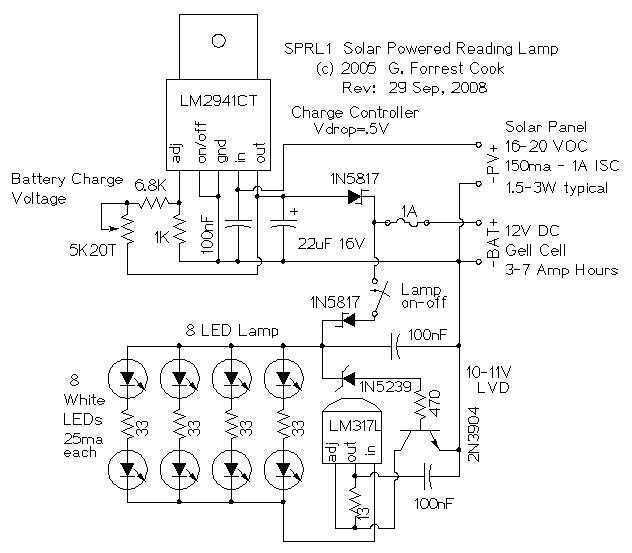
The reading lamp consists of a small solar panel, a standard UPS style lead acid battery, and an LED circuit board. The circuit board contains a low power solar charge controller (regulator), a set of 8 white LEDs, a...
A project of a 555 tester circuit, the circuit will start blinking LEDs when power is applied, which will indicate that the IC is working correctly. The 555 tester circuit is designed to verify the operational status of the 555...

Alarm system designs often require circuitry that can detect whether a phone line is active or broken. The primary challenge in this design is to draw less than 5 µA from the phone line, which operates within a voltage...
The ML4423 is an integrated controller designed for single-phase and two-phase AC induction motors. It features PWM (Pulse Width Modulation) capabilities for speed control and includes various protection circuits such as short circuit protection, fire protection, and a reference...
The circuit is straightforward yet capable of outstanding performance. It has been specifically designed as an amplifier for the digital sound card in a computer. Audio input can be sourced from any two-channel line-level device such as a television,...
The following circuit illustrates the AT90LS2323 Microcontroller Circuit Diagram. Features include a voltage range of 2.7 to 6 volts, and compatibility with all 2323 chips. Components are included. The AT90LS2323 microcontroller circuit is designed to operate within a voltage range...