
Circuit Detects Phone-Line Breaks

The alarm system circuit operates by monitoring the status of the telephone line and detecting changes in its condition. The micropower oscillator generates a signal that is indicative of the line status, ensuring that the current draw remains below the specified threshold. The use of high-voltage capacitors allows for effective isolation between the oscillator and the detection circuit, preventing interference while maintaining the necessary performance characteristics.
The astable multivibrator configuration of the oscillator is essential for generating the required oscillation frequency without the drawbacks of traditional resistive methods. The careful selection of current sources and capacitors ensures that the circuit remains responsive while consuming minimal power. The full-wave rectification and smoothing processes further stabilize the biasing of the oscillator, enhancing its reliability.
In terms of circuit design, the implementation of a half-wave rectifier for charging the capacitor is a strategic choice, as it optimizes the charging process while avoiding the complications associated with high-value resistors. The MOSFET output stage is designed to provide a robust interface to downstream components, ensuring that signal integrity is maintained.
Overall, the design emphasizes efficiency, reliability, and compliance with regulatory standards, making it suitable for alarm systems that require continuous monitoring of telephone line status. The careful consideration of component ratings, layout, and isolation techniques contributes to the robustness of the system, ensuring that it functions effectively in a variety of operational conditions.Alarm system designs often require circuitry that can detect whether a phone line is active or broken. With this type of design, the primary difficulty is drawing less than 5 µA from the phone line over a line-voltage range of 24 to 58 V as the standard dictates.
When the phone is in its "on-hook" state, the central office exchange (CO) acts as a current source. The circuitry on the line is restricted to impedances that create less than a 5- µA current from this source. When the phone goes off-hook, the phone`s impedance lowers significantly. Consequently, a CO-detected voltage drop is produced. The CO creates the ringing signal by adding a low-frequency signal to this dc bias signal. Shown here is a circuit based on a micropower oscillator biased by the telephone line ( see the figure ).
This oscillator generates a differential signal, which is coupled to a detector circuit via high-voltage capacitors. These capacitors supply the required isolation. The detection circuit merely recognizes the presence of the oscillation while presenting negligible output loading to the oscillator itself.
The oscillator uses an astable multivibrator. Instead of relying on the traditional collector resistors, which would otherwise become very large, it employs 1- µA current sources (Q4 and Q6). These determine the supply current. Also, capacitor-charging resistors (which establish the oscillation frequency) are based upon current sources of 0.
1 µA nominal (Q3 and Q5). A full-wave rectifier (D1, D2, D3, and D4) and a smoothing capacitor (C6) bias the oscillator from the phone line. C6 has strong impact on the time needed to detect a line break due to the high impedances involved in this circuit.
To meet the galvanic isolation requirements for telephones, the oscillator section must be isolated from the detection circuitry. Traditionally, this has been achieved by means of a transformer. In addition to its cost and size penalties, the transformer is unable to couple dc current, which is needed for detection when the phone remains "on-hook.
" At this point, capacitor coupling comes to the rescue. Low-capacitance, high-voltage devices couple the oscillator to the externally supplied detector circuitry. Normally, a capacitor such as C5 would be discharged by the Q7 current source (0. 1 µA nominal). But the detector in this application contains a half-wave rectifier that charges C5. This is a better solution than using a simple resistor, which would require a very high value (i. e. , greater than 100 M ©). Finally, a low-impedance output is provided by means of a MOSFET device. Since the MOSFET includes a gate-source zener diode, it`s necessary to employ a large gate resistor. Doing so will prevent excessive loading when it enters the conduction region. The possibility of high voltage levels in the phone lines determines the ratings of the devices to use.
Otherwise, the component values are noncritical. To reduce leakage effects, very high valued resistors (over 10 M ©) should be implemented by means of multiple 10-M © resistors in series. Solder flux must be carefully cleaned. This will prevent leakage around the resistors between the component pads on the printed-circuit (pc) board.
Also, pc-board layout must be well planned to minimize the effect of external noise sources caused by the high impedances involved. 🔗 External reference
Related Circuits

This circuit is designed for sound detection and generates an output signal when sound is detected. This output can trigger another circuit that activates an alarm, making it suitable for security applications. The circuit employs a condenser microphone to...
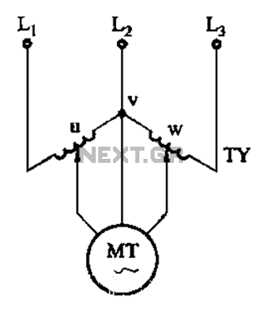
The circuit shown in Figure 3-177 utilizes two single-phase voltage regulators connected to a V-shaped configuration of single-phase regulators. This setup allows for the simultaneous adjustment of voltage and balance, enabling performance akin to a three-phase balanced adjustment. The circuit...
This circuit provides a visual 9-second delay using 10 LEDs before closing a 12-volt relay. When the reset switch is closed, the 4017 decade counter is reset to the 0 count, illuminating the LED driven from pin 3. The...
Probably the easiest way of doing automatic switch off is with relay logic. In the diagram, the box marked RL1 is the coil, the 2 in the coil box tells you there are two sets of contacts somewhere on...

The quality of the sine wave depends on how closely the components in the twin-T network are matched in the operational amplifier's feedback loop. The twin-T network is a type of filter circuit commonly used in audio applications, signal processing,...

VOX is a voice-activated switch commonly used with microphones as an alternative to traditional push-button switches. The VOX can be connected to various audio equipment featuring an external speaker for coupling. The activation threshold is adjusted using the volume...