
Dual-Tone (Frequency) Decoder (Detector)
 Decoder (Detector)")
This circuit is designed to detect and respond to a specific combination of audio frequencies, utilizing a frequency detection mechanism. The input stage typically consists of a microphone or audio signal input, which captures the sound waves. The circuit processes these signals through a bandpass filter, which is configured to isolate the desired frequency range based on the values of resistors and capacitors.
The resistor R1 plays a crucial role in setting the cutoff frequency of the filter, alongside other components such as capacitors (C1, C2) and potentially additional resistors (R2, R3). The relationship between these components can be expressed using the standard formula for the cutoff frequency of an RC filter, which is given by:
\[ f_c = \frac{1}{2\pi R C} \]
where \( f_c \) is the cutoff frequency, R is the resistance, and C is the capacitance. By adjusting the values of R1 and the associated capacitors, the circuit can be tuned to respond specifically to the mixed tones.
Once the desired frequencies are detected, the output stage of the circuit is activated. This output can be configured to drive an LED indicator, trigger a relay, or send a signal to a microcontroller for further processing. The activation mechanism may utilize a comparator or an operational amplifier configured as a Schmitt trigger to ensure a clean transition and minimize false triggering due to noise.
Overall, this circuit serves as a frequency detection system that can be applied in various applications, including audio processing, communication systems, and sound-based control mechanisms. The careful selection of component values is essential to ensure the circuit operates effectively within the intended frequency range.The output of this circuit will be activated when a mix of two tone/frequency is detected on the input. The frequency f is determined by the values of R1 and.. 🔗 External reference
Related Circuits
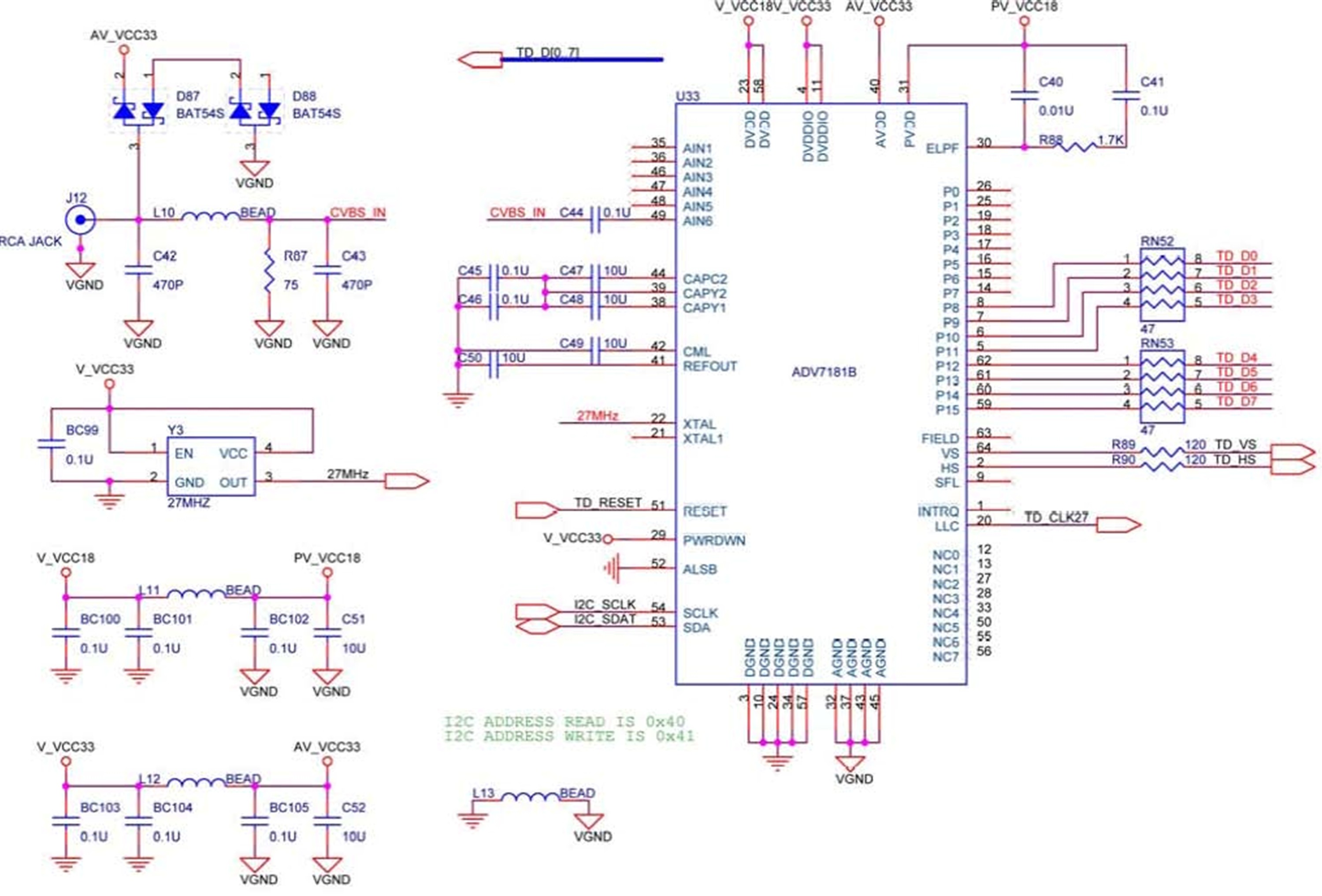
The DE2 board features an Analog Devices ADV7181 TV decoder chip. The ADV7181 is an integrated video decoder that automatically detects and converts standard analog baseband television signals (NTSC, PAL, and SECAM) into 4:2:2 component video data, which is...
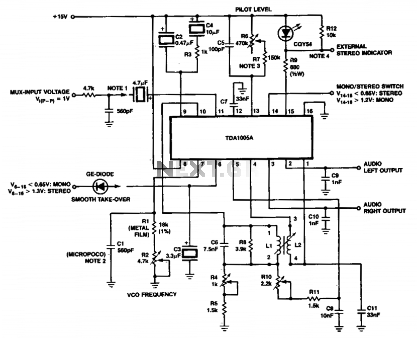
For other input structures, refer to Figures 6 to 11, which illustrate various configurations. The micropoco capacitor has a temperature coefficient of 125.10^-6 i 60.10^k^-1. In simplified circuits, a fixed resistor (e.g., 620kΩ) can be employed to ensure a...
An LM556 dual oscillator/timer, U1, configured as a two-tone oscillator drives U2, a dual 4-watt amplifier. One of the oscillators, pins 1 to 6, contained in U1 produces the upper frequency signal of about 200 Hz, while the second...
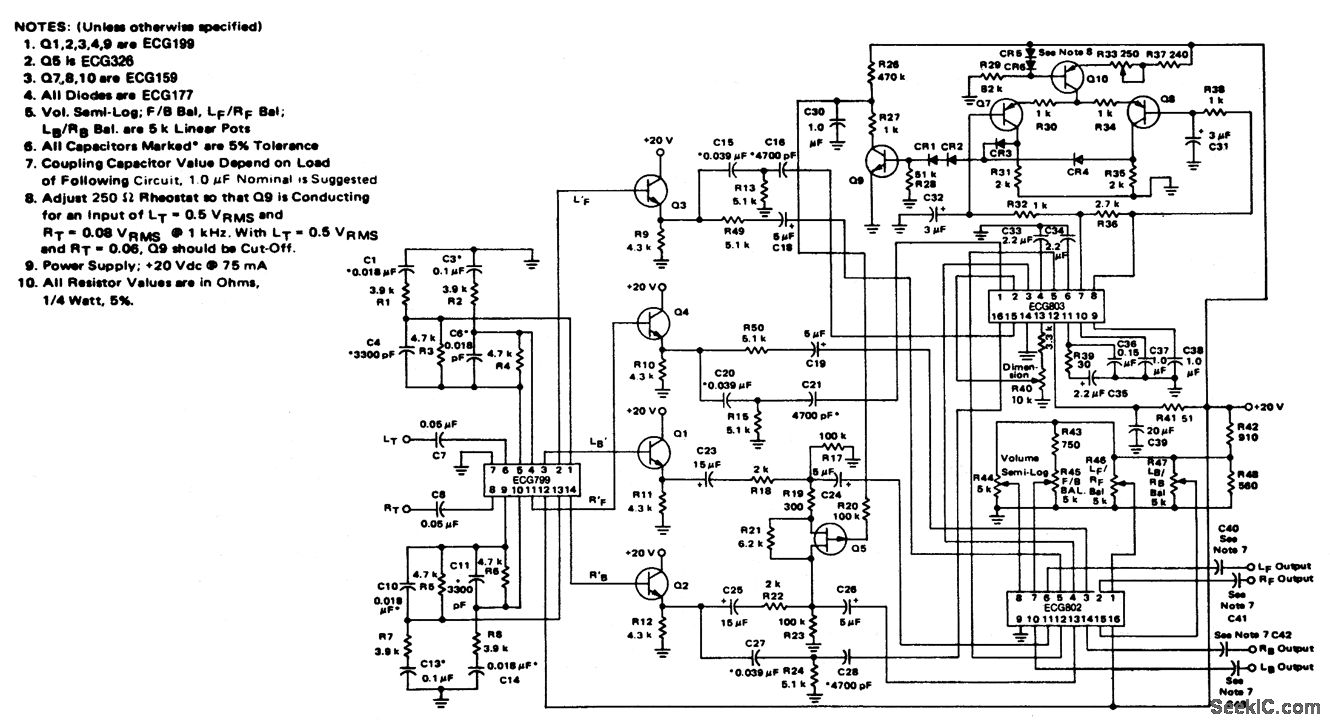
4-channel SQ logic decoder with a current drain of 75 mA at 20 volts. The input impedance is 2M ohms, and the output impedance is 2K ohms (courtesy of GTE Sylvania Incorporated). The 4-channel SQ logic decoder is an integrated...
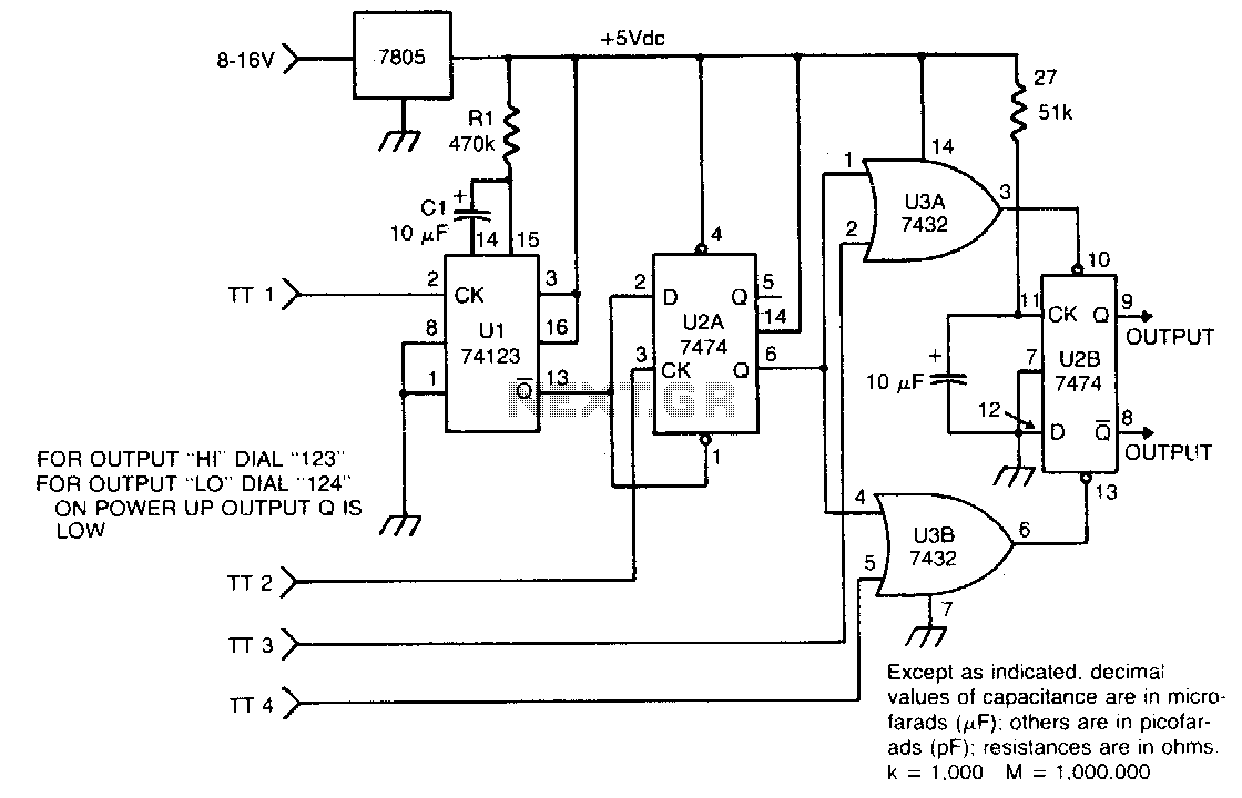
The circuit takes active low inputs from a Touch Tone decoder and reacts to a proper sequence of digits. The proper sequence is determined by which Touch Tone digits the user connects to the sequence decoder inputs TT1, TT2,...
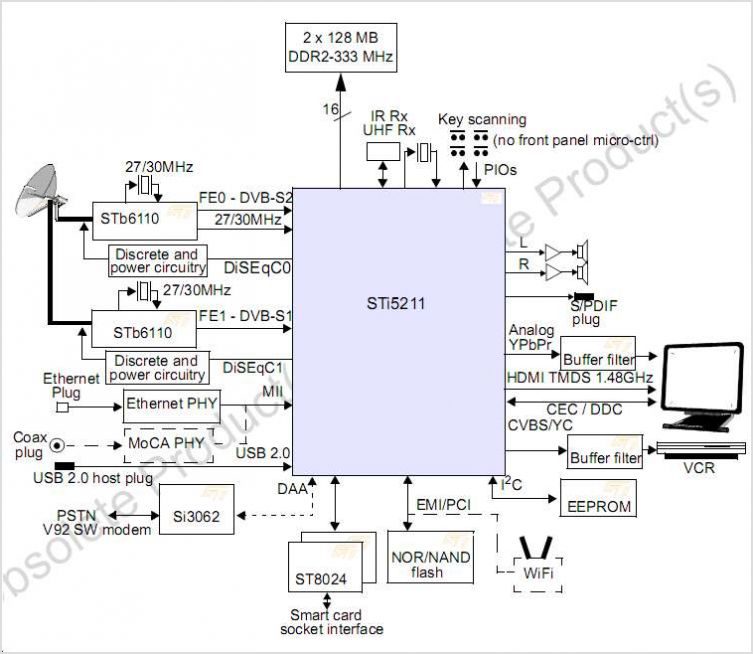
The STI7167 utilizes advanced process technology to deliver a fully featured HD AVC DVB-C and DVB-T demodulator and decoder integrated circuit (IC). This highly integrated system-on-chip is designed for set-top box (STB) markets across cable, terrestrial, and terrestrial/IP hybrid...