
4-channel SQ logic decoder

The 4-channel SQ logic decoder is an integrated circuit designed to decode binary inputs into a single active output line corresponding to the binary value of the inputs. This device operates with a current drain of 75 mA when powered at 20 volts, making it suitable for applications where moderate power consumption is acceptable.
The input impedance of 2M ohms ensures that the decoder can interface with a variety of signal sources without significantly loading them down, allowing for better signal integrity. Conversely, the output impedance of 2K ohms facilitates compatibility with standard logic levels and ensures that the decoder can drive subsequent stages effectively without introducing significant voltage drops or signal degradation.
In practical applications, this logic decoder can be utilized in digital circuits where multiple binary inputs need to be converted into a single output line for further processing. It is particularly useful in applications such as data routing, multiplexing, and control systems where the selection of one output from several inputs is required.
The device's design incorporates features to ensure reliable operation across its specified voltage range, and its low power consumption makes it ideal for battery-operated devices. Proper layout and decoupling techniques should be employed in circuit design to minimize noise and ensure stable operation of the logic decoder within the intended application.4-channel SQ logic decoder. Current drain is 75 mA at 20 volts. Input impedance is 2M, while output impedance is 2K (courtesy GTE Sylvania Incorporated). 🔗 External reference
Related Circuits
Both specifications were contradictory; a large display would require a significant amount of power, while the intention was to use the smallest battery for the longest duration. The solution was to separate the power supply for the logic and...
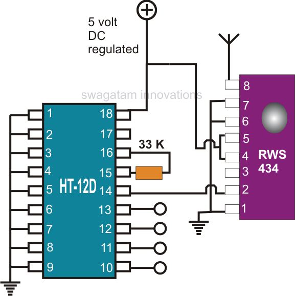
Creating a universal remote control system has become quite straightforward. One can acquire the necessary chips, assemble them, and the high-tech remote control device will be operational. This document discusses specific remote control chips designed for this purpose. The...
The 5 volt regulated power supply for TTL and 74LS series integrated circuits has to be very precise and tolerant of voltage transients. These ICs are easily damaged by short voltage spikes. A fuse will blow when its current...

The circuit presented utilizes NAND logic gates from the Hitachi HD series, specifically the HD74LS00, which is a quad NAND integrated circuit. A special technique has been implemented to achieve three-state operation using a single IC. Gate N1 is...
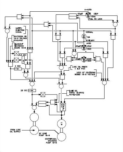
The use of logic symbols results in a diagram that allows users to determine the operation of a component or system as various input signals change. To read and interpret logic diagrams, one must understand the meaning of each...

A resistive voltage divider is utilized to establish a bias voltage for the input (pins 2 and 3). The demodulated FM signal is introduced to the input through a two-stage high-pass filter, which serves to provide capacitive coupling and...