
dual-trace scope switch

The described circuit configuration involves a switcher output interfacing with an oscilloscope to facilitate the observation of signal characteristics. The switcher output provides a voltage signal that is directed to the vertical input of the oscilloscope, allowing for real-time analysis of the waveform. The external-sync input is utilized to synchronize the oscilloscope's display with the input signal, ensuring accurate timing and phase representation.
The input amplifiers play a crucial role in determining the frequency response of the circuit. With a standard frequency response of 300 kHz, these amplifiers are capable of handling a range of signal amplitudes and frequencies effectively. The gain controls allow for adjustment of the input signal's amplitude, providing flexibility in signal processing. When the gain controls are set to their maximum position, the circuit exhibits an enhanced frequency response capability of up to 1 MHz. This characteristic is particularly beneficial for applications that require the analysis of high-frequency signals, as it enables the observation of rapid signal variations without distortion.
In summary, this circuit design is optimized for high-frequency signal analysis, leveraging the capabilities of the oscilloscope and input amplifiers to achieve precise measurements and observations across a wide frequency range. The synchronization feature further enhances the reliability of the measurements, making this setup suitable for various electronic testing and diagnostic applications.The switcher output goes to the single vertical input of the scope, and a sync line from one of the inputs is taken to the scope's external-sync input. Frequency response of the input amplifiers is 300 kHz over the range of the gain controls. With the gain controls wide open so no attenuation of the signal takes place, the frequency response is up to 1 MHz.
Related Circuits
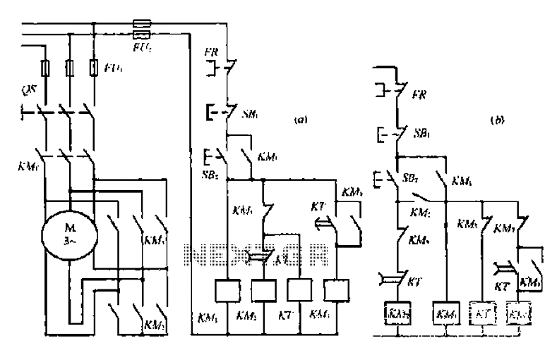
A star-delta switch is utilized for starting circuits, commonly depicted in Figure I-5 (a) of the knife wiring. While this method is effective, it poses security risks. When the motor starts, it can create significant voltage fluctuations that may...
A switch that is controlled by its ambient temperature operates without human intervention, except during the assembly of the electronic thermostat. This thermally controlled switch has numerous practical applications. For instance, if the internal temperature of a computer rises...
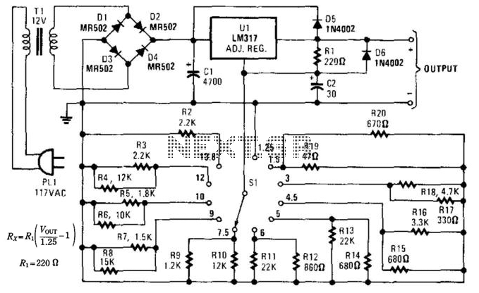
This supply can function as a battery eliminator for various devices, such as tape recorders, small radios, clocks, and more. A resistance is selected to provide a predetermined output voltage. In this circuit, various commonly used supply voltages produced...
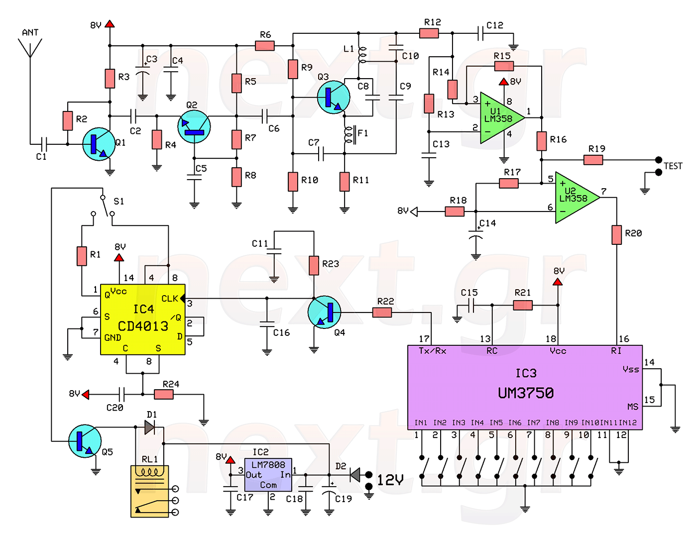
This circuit includes a 2048 radio remote control transmitter and a corresponding wireless receiver that features high reception sensitivity and low power consumption. The combination of these two components provides a highly reliable remote control system, suitable for various...
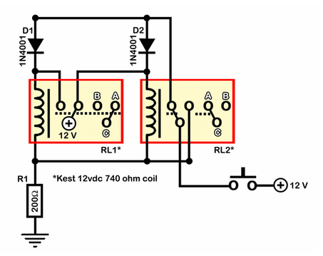
A relay circuit functions as a double-pole double-throw (DPDT) toggle, controlled by a momentary switch. The design emphasizes simplicity with minimal integration of components such as 555 timers or transistors. The circuit is depicted in an active state. Half...
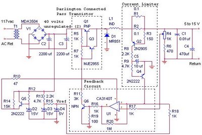
The switching power supply provides 12 volts at a maximum of 10 amps, utilizing a discrete transistor regulator with an operational amplifier acting as a comparator in the feedback circuit. The schematic does not depict the front panel power-on...