
RF Remote Control Switch Rx-Tx circuits

The reliability and security of the transmitter-receiver cooperation are notable. The 2048 code combinations provided by the dip switches and the integrated digital encoder in the transmitter ensure that the remote control system is secure, activating only when the transmitter and receiver share identical codes. The operational range of the system is approximately 80 meters in open air.
The technical specifications of the transmitter include:
- Power supply: 12V DC (Battery)
- Power consumption: 12mA maximum
- Operating frequency: 320-360 MHz
- Range: 60-80 meters (in visual contact)
- Codes: 2048
- LED action indicator
The transmitter circuit is supported by an integrated IC1 (coding) circuit and the Q1 transducer, which acts as the oscillator. The integrated IC1 is a digital encoder housed in an 18-pin MOS/LSI package. The only external components required are resistor R1 and capacitor C2 for internal timing.
The broadcast code is determined by the dip switches, providing 2048 codes for enhanced security. Each switch corresponds to a bit of 0.96 milliseconds, resulting in a digital word duration of 11.52 milliseconds (0.96 x 12). This digital word generates the RF oscillator, which is of the Colpitts type, with its frequency set by coil L1 and variable capacitor C4.
Variable capacitor C4 adjusts the transmit frequency to match that of the receiver. Capacitor C3 is used to provide positive feedback to the RF oscillator, ensuring sustained oscillations. Choke F1 prevents RF frequencies from interfering with the supply voltage to IC1, while capacitor C1 decouples the transmitter's supply voltage. An LED provides a visual indication of the transmitter's operation whenever the transmit button S1 is pressed.
The components for the transmitter include:
- R1 = 1MΩ
- R2 = 33KΩ
- C1 = 1nF CERAMIC
- C2 = 47pF CERAMIC
- C3 = 3.3pF CERAMIC
- C4 = 2-10pF Trimmer
- F1 = 1µH choke
- IC1 = UM3750
- S1 = push button
- D1 = LED
- Q1 = BF199 NPN TRANSISTOR
Connections for the transmitter operation involve installing a 12V miniature battery with correct polarity, powering the remote control receiver, and setting the dip switch codes to match between the transmitter and receiver. The transmitter should be positioned about one meter from the receiver while pressing the S1 button. Using a plastic screwdriver, the variable capacitor C4 should be adjusted until the relay in the receiver is energized.
The technical specifications of the receiver include:
- Operating voltage: 11-14V DC
- Power consumption: 12mA to 30mA (maximum)
- Operating frequency: 320-360 MHz
- 2048 different broadcast codes
- Relay contacts: 250V / 2A
- Remote control range: 80 meters with visual contact
- Direct collaboration with the transmitter
The receiver circuit comprises five transistors, three integrated circuits, and various resistors, capacitors, and auxiliary components. The Q1 transistor serves as the main high-frequency amplifier (RF amplifier), which boosts the signal from the antenna. The BFR96 transistor utilized in this stage provides high gain (18-20 dB) with minimal noise (2 dB), essential for effective reception.
The amplified antenna signal from the output of Q1 is directed to Q2, configured in a common base circuit. Although this configuration does not yield maximum amplification, it achieves an excellent interface between RF transistor Q1 and transistor Q3. Transistor Q3 functions as an oscillator-mixer and overcurrent detector, with the receiving frequency determined by the LC circuit formed by coil L1 and capacitor C10. Capacitor C8 maintains oscillations in transistor Q3, while choke F1 minimizes external noise.
The output signal from transistor Q3 undergoes demodulation before being amplified by power amplifiers A1 and A2, which filter and modulate the signal before passing it to the integrated IC3 for decoding. The output of power amplifier A1 serves as a control point for transmitter adjustment, allowing verification of frequency alignment using a frequency meter.
Integrated circuit IC3 decodes the input signal, relying on external components R21 and C15 for internal timing. The termination code is determined by a 10-position dip switch and two permanent short circuits on IC3. The output of IC3 activates only when the received code matches the transmitted code, which switches the output from HIGH to LOW.
This state disables transistor Q4, allowing a positive voltage through resistor R23 to the S1 switch and IC4 clock terminal. The output from integrated IC4, a flip-flop, controls the S1 switch, determining output states based on remote control receiver activation. In the ON-OFF position, it activates the relay RL via transistor Q5 only while receiving the correct signal. If the switch is set to ON and the correct activation signal is received, the relay is continuously activated. Diode D1 protects transistor Q5 against reverse currents from the relay coil.
Integrated circuit IC2 acts as a voltage stabilizer, providing +8V DC to the receiver circuit, excluding the output stage. This ensures consistent operating voltages under varying supply conditions, enhancing circuit reliability. Diode D2 safeguards the circuit from reverse voltages from the power supply.
The components for the receiver include:
- R1, R7, R8, R9, R13, R14, R22, R23 = 10KΩ
- R2 = 47KΩ
- R3, R5, R24 = 1KΩ
- R4 = 270Ω
- R6, R12, R16, R17 = 4.7KΩ
- R10 = 3.3KΩ
- R11 = 470Ω
- R15 = 2.2MΩ
- R18, R21 = 1MΩ
- R19 = 4.7Ω
- R20 = 12KΩ
- C1, C2 = 270pF CERAMIC
- C3, C13, C14 = 10µF/16V ELECTROLYTIC
- C4 = 680pF CERAMIC
- C5, C9 = 100pF CERAMIC
- C6 = 2.7pF CERAMIC
- C7, C11, C16 = 1nF CERAMIC
- C8 = 3.3pF CERAMIC
- C10 = 2.7pF CERAMIC
- C12 = 4.7nF CERAMIC
- C15 = 47pF CERAMIC
- C17, C18 = 100nF MKT
- C19 = 220µF/25V ELECTROLYTIC
- C20 = 15nF CERAMIC
- F1 = 1µH choke (BROWN-BLACK-GOLD)
- D1, D2 = IN4007
- Q1, Q2 = BFR96 NPN
- Q3 = BF199 NPN
- Q4, Q5 = BC548, BC547 NPN
- IC1 = LM358
- IC2 = LM7808 Regulator
- IC3 = UM3750
- IC4 = CD4013 flip-flop
- RL = 12V relay (250/2A contacts)
Construction of the receiver involves creating a coil L1 from 1mm silver wire, shaped into two reversed "U" forms, with a height of 6mm and a length of 8mm. An antenna wire of 20-30cm should be attached. After connecting the receiver power supply and setting switch S1 to ON, the dip switch code must match that of the transmitter.
If the transmitter and receiver frequencies align and the codes match, the relay will activate while the transmitter button is pressed. If the frequencies do not match, the transmit frequency must be adjusted to align with the receiver's frequency. This adjustment involves positioning the transmitter one meter away, pressing the transmit button, and tuning capacitor C4 until the voltmeter indicates the minimum value, confirming frequency synchronization.This circuit consists of a 2048 radio remote control transmitter and the corresponding wireless receiver with very high reception sensitivity and low consumption. The combination of the two above gives a high-reliability remote control, ideal for security systems, alarms, automation, etc.
At home, in the car and elsewhere. Using the wireless remote control system is done by simply pressing the button on the transmitter. Its operation is based on the use of radio waves that offers advantages over other modes of remote control such as the most common infrared rays, giving us a wider range of operation and smaller problems when sending the signal through physical obstacles that may be between transmitter and receiver. Any mechanism such as a garage door, an alarm system or any other industrial automation can be easily connected to the relay output, making it easy to use and control any desired devices.
The reliability and security offered by the transmitter and receiver co-operation is sufficient. The 2048 code combinations from the dip switches on the one hand and the integrated digital encoder of the transmitter on the other, make this remote control system absolutely safe as it will only be activated when the transmitter and receiver have exactly the same codes. The operating range of the system is about 80 meters (in open air).
The technical characteristics of the transmitter are:
- Power supply: 12V DC (Battery)
- Power consumption: 12mA max
- Operating frequency: 320-360MHz
- Range: 60-80m (in visual contact)
- Codes: 2048
- LED action indicator:
Description of the transmitter circuit:
The radio remote control transmitter supports its operation on the integrated IC1 (coding) circuit and the Q1 transducer that is the oscillator.
Integrated IC1 is an digital encoder in a 18pin MOS / LSI shell. The only external components needed are the resistor R1 and the capacitor C2 for the internal timing.
The broadcast code is determined by the dip switches which give 2048 codes, thus ensuring high security standards. Each switch specifies a bit of 0.96 msec. The bits of the 12 switches define a digital word of duration (0.96 x 12) 11.52 msec. This digital word forms the RF oscillator. This oscillator is Colpitts type and its frequency is determined by the coil L1 and the variable capacitor C4.
Variable capacitor C4 sets the transmit frequency so that it is the same as the frequency set to receive the radio remote control receiver.
The C3 capacitor serves to generate positive feedback on the RF oscillator to achieve maintenance of the oscillations.
Chock F1 prevents the RF frequency of the oscillator from entering the supply voltage of the integrated circuit IC1 and causing problems. Capacitor C1 helps decoupling the transmitter's supply voltage. Finally, the LED gives a visual indication of the transmitter operation every time the transmit button is pressed with S1.
The components for the transmitter:
R1 = 1MΩ
R2 = 33KΩ
C1 = 1nF CERAMIC
C2 = 47pF CERAMIC
C3 = 3.3pF CERAMIC
C4 = 2-10pF Trimmer
F1 = 1 μH chuck
IC1 = UM3750
S1 = push button on
D1 = Led
Q1 = BF199 NPN TRANSISTOR
Connections - Transmitter Operation:
Install a 12V miniature battery, taking care for the correct polarity position.
Power supply the remote control receiver. Place the code from the dipswitch switches, which should of course be the same on both the transmitter and the receiver. Advance the transmitter within a distance of about one meter from the reception by pressing the S1 button.
With a plastic screwdriver, rotate the variable capacitor C4 slowly until the relay in the receiver is energized.
At this point the transmission frequency is the same as the reception. For best results and for longer range, use the test terminals of the receiver. Connect a DC voltmeter. With the transmitter approximately one meter apart and holding down the transmit button, adjust the variable capacitor C4 with a plastic screwdriver so that the voltmeter shows the minimum value of about 2 - 2.5V.
Then the transmission and reception frequencies are the same.

The schematic diagram of RC Transmitter
Technical Characteristics of the Receiver:
- Operating voltage: 11 - 14V DC
- Power consumption: 12mA at 30mA (max)
- Operating frequency: 320 - 360 MHz
- 2048 different broadcast codes
- Relay contacts: 250V / 2A
- Remote control range 80m with visual contact
- Direct collaboration with the transmitter
Receiver Circuit Function Explanation:
The electronic circuit diagram of the receiver, consists of 5 transistors, 3 integrated, and a plurality of resistors, capacitors and other auxiliary components. Q1 transistor is the main high frequency amplifier (RF amplifier). This boost step has the input antenna and the type of transistor it uses (BFR96) ensures high gain (18 - 20 dB) with very low noise (2 dB), which is necessary for the receiver.
The amplified antenna signal from the output of Q1 via capacitor C2 is driven to Q2 which is in a common base circuit.
Although this link does not provide the maximum amplification, it provides us with an excellent fit between RF transistor Q1 and transistor Q3.
Transistor Q3 is the main receiver used as a oscillator-mixer and overcurrent detector. The receiving frequency is determined by the coordinated LC circuit that forms the coil L1 and the capacitor C10.
C8 capacitor keeps the oscillations in transistor Q3. The F1 chock on the transducer Q3 reduces any external noise and signals that would likely cause reception problems by reducing the sensitivity of this segment.
The signal from the output of transistor Q3 and after being demodulated by the high reception frequency is led to the two power amplifiers A1 and A2 which, after amplifying it, filter and modulate it properly lead it through the resistor R20 to the integrated IC3 which will make the decoding at the received signal.
At the same time, however, the output of the power amplifier A1 through the R19 resistor gives us a control point and adjustment of the transmitter. Thus, at any time, we can check whether the transmitting frequency is the same as the receiver receives using a frequency meter.
The IC3 integrates the decoding of the input signal. The only external components needed for its operation are resistance R21 and capacitor C15 for the internal timing.
The termination code is determined by 12 short positions (J1 - J10) through a 10-position dip switch and two permanent short-circuits on the IC3 integrated poles 11 and 12. The IC3 integrated circuit just accepts 4 times the code that specifies J1 - J10 activates its output.
Thus we have drastically reduced possibilities of interaction between adjacent remote control systems.
The receiving code should be exactly the same as the broadcast code in order to enable the output of the integrated IC3 circuit. As soon as the integrated IC3 circuit is activated its output (pin 17) switches from HIGH to LOW.
This state disables the transistor Q4 resulting in a positive voltage being applied by the resistor R23 at one end of the S1 switch and the IC4 terminal clock.
The output of the integrated IC4 (pin 1) which is a flip flop feeds the other end of switch S1 via resistor R1.
Switch S1 determines output states depending on activation of remote control receiver. In the ON-OFF position it activates the RL relay (via transistor Q5) only for as long as the receiver receives the correct signal from the transmitter (momentarily).
If the switch is in the ON position and the receiver receives the correct activation signal it activates the RL relay (again via transistor Q5). The relay is switched off as soon as the receiver receives a new (and correct reception code) signal.
Diode D1 protects transistor Q5 from reverse currents generated by the RL relay coil during operation.
Finally, the IC2 integrated circuit is a voltage stabilizer at + 8V DC which feeds the entire receiver circuit with the exception of the output stage (transistor Q5 and RL relay) giving the receiver circuit constant operating voltages under different supply voltages to ensure high Reliability of the circuit. The D2 diode protects the circuit from any inverse voltages coming from the power supply circuit.
The Components for the receiver
R1,R7,R8,R9,R13,R14,R22,R23 = 10KΩ
R2 = 47KΩ
R3,R5,R24 = 1KΩ
R4 = 270Ω
R6,R12,R16,R17 = 4,7KΩ
R10 = 3,3KΩ
R11 = 470Ω
R15 = 2.2MΩ
R18,R21 = 1MΩ
R19 = 4.7Ω
R20 = 12KΩ
C1,C2 = 270pF CERAMIC
C3,C13,C14 = 10μF/16V ELECTROLYTIC
C4 = 680pF CERAMIC
C5,C9 = 100pF CERAMIC
C6 = 2.7pF CERAMIC
C7,C11,C16 = 1nF CERAMIC
C8 = 3,3pF CERAMIC
C10 = 2,7pF CERAMIC
C12 = 4,7nF CERAMIC
C15 = 47pF CERAMIC
C17,C18 = 100nF MKT
C19 = 220μF/25V ELECTROLYTIC
C20 = 15nF CERAMIC
F1 = 1μH chock (BROWN-BLACK-GOLD)
D1,D2 = IN4007
Q1,Q2 = BFR96 NPN
Q3 = BF199 NPN
Q4, Q5 = BC548, BC547 NPN
IC1 = LM358
IC2 = LM7808 Regulator
IC3 = UM3750
IC4 = CD4013 flip-flop
RL = relay 12V (250/2A contacts)
Construction - Operation - Receiver settings:
The coil L1 is made of 1mm silver wire and forms two reversed "U" when mounted on the board. Its height is 6mm while its length is 8mm.
Attach a piece of 20-30cm wire for antenna. Connect the receiver power supply and set the S1 switch to ON, then set the same code as the transmitter (from the dip switch).
If the operating frequency (set by the transmitter) is the same between the transmitter and the receiver and the receiver code is identical to that of the transmitter, then the relay will be switched on by leaving the transmitter button the relay is deactivated.
If the operating frequency is not the same between the transmitter and receiver, set the transmit frequency again to match the receiving frequency of the receiver.
This setting is as follows: With the transmitter approximately one meter apart and holding down the transmit button, adjust the variable capacitor C4 of the transmitter with a plastic screwdriver so that the voltmeter connected to the receiver shows the minimum value. At this point the transmit and receive frequencies are the same.
Happy soldering ;)
Related Circuits
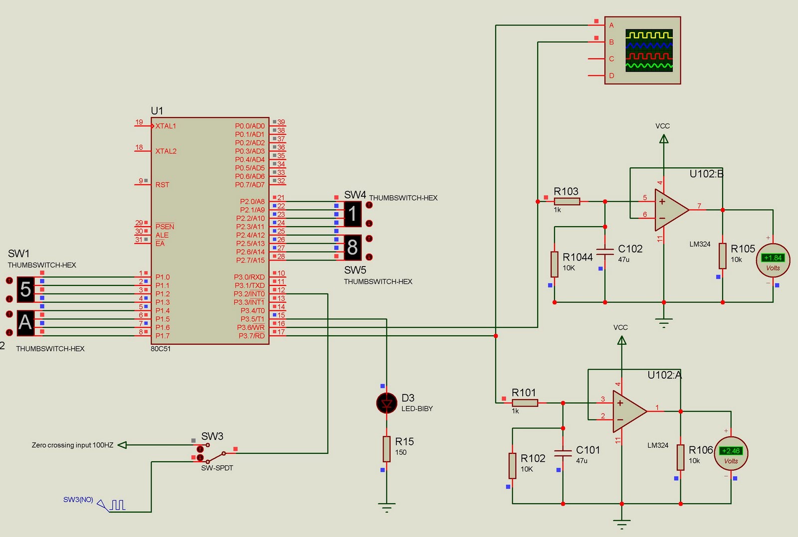
This project currently outputs two PWM signals but can be easily extended to generate multiple PWM signals. The input to the microcontroller consists of 100Hz pulses serving as zero-crossing signals. It is designed for a two-channel DAC, where the...

Transistors are essential components of electronic circuits. The success of a circuit design depends on the selection of the appropriate transistor type and the calculations involved. Transistors serve as fundamental building blocks in electronic circuits, playing critical roles in amplification,...
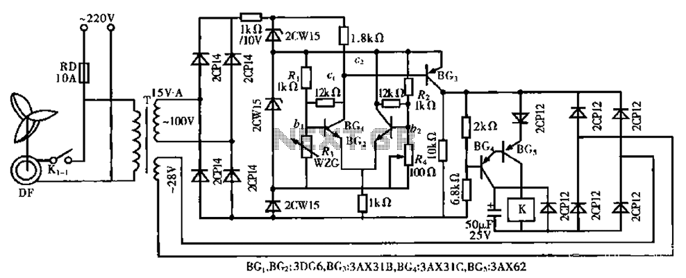
The circuit is a bistable circuit where each bistable unit is controlled by high and low output levels. When power is supplied to the circuit, current flows through components R13, CL, and VD to VD2 for full-wave rectification. The...

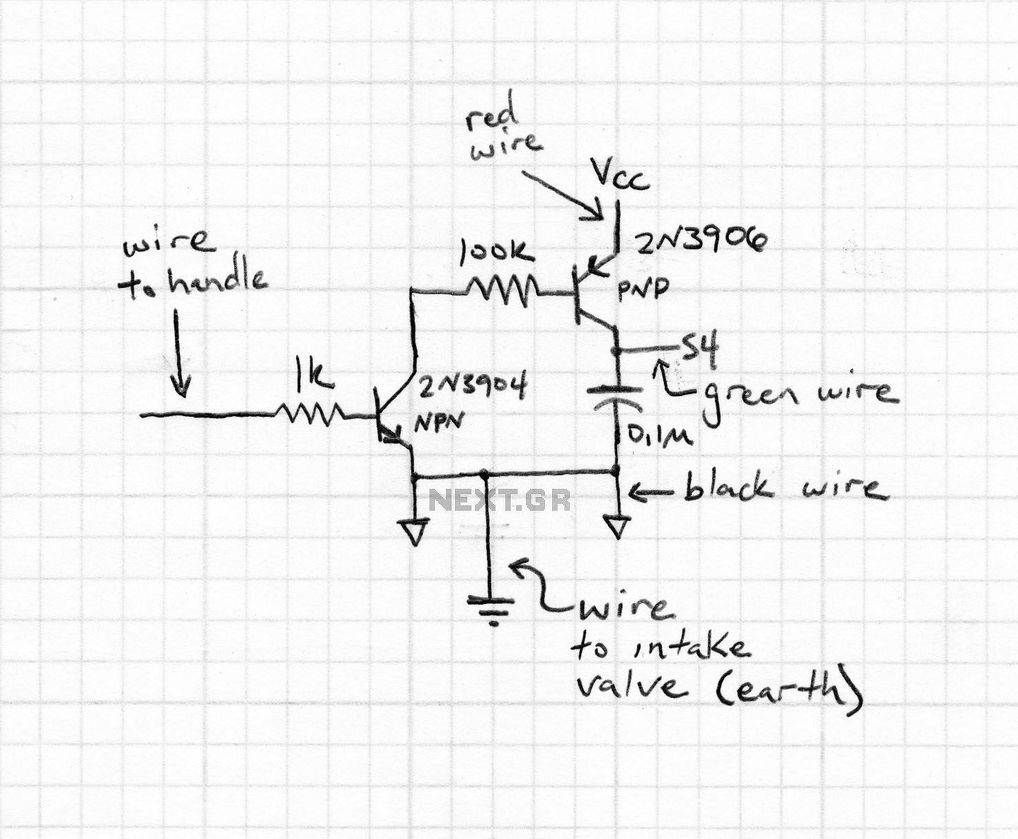
The following method allows the timer to be triggered by a normally closed switch. This would be useful in applications such as intrusion alarms where the protection circuit is broken if a window or door is opened. Trigger Input...
The first phase of a motion-controlled photography rig has been completed, focusing on the setup of bipolar stepper motor controllers. This component is crucial for motor control, which is essential for achieving motion in the project. A list of...
Both halves of the circuit are identical. Both inputs have a DC path to ground via the input 47k control, which should be a dual logarithmic type potentiometer. The balance control is a single 47k linear potentiometer, which, when...