
Dual-trace, triggered oscilloscope

The project involves a dual-trace, triggered oscilloscope that utilizes a combination of analog and digital technologies, originally based on a vacuum tube architecture. The core of the design includes a cathode ray tube (CRT) for display, which is powered by a high voltage supply retained from the original oscilloscope chassis. The dual-trace capability allows for the observation of two signals simultaneously, which is essential for comparative analysis in various electronic applications.
The design emphasizes the importance of understanding the underlying principles of oscilloscope operation rather than strictly following the schematics. Experienced designers are encouraged to adapt the circuit to incorporate modern components such as high-speed operational amplifiers and signal drivers, which can significantly enhance performance, particularly in terms of bandwidth. The original design supports bandwidths beyond 100 MHz when modified appropriately.
Key features of the oscilloscope include a triggered sweep mechanism that stabilizes the display of repetitive signals, enabling accurate measurements and analysis. Additionally, the design allows for the integration of delayed sweep functionality, which is advantageous for examining transient events in greater detail. The schematics provided serve as a foundational reference for designers looking to innovate and improve upon the traditional oscilloscope design, promoting a deeper understanding of both analog and digital signal processing techniques.This site contains public-domain schematics for a dual-trace, triggered oscilloscope, and some theory. Click on the topic in the table below to see the schematic for that block. I designed and built this oscilloscope in 1986 using the chassis of a non-working vacuum tube oscilloscope, keeping only the original high voltage vacuum tube supply and CRT.
This construction project is only for the experienced designer, since you will want to change and adapt parts of the circuit to accommodate new semiconductors and devices. I recommend that you do not build an oscilloscope from these schematics, but rather, understand the design principles and come up with a more modern design.
The bandwidth can easily be extended beyond 100 MHz by using inexpensive high speed drivers and op-amps. Delayed sweep, and other features, are easy to add. 🔗 External reference
Related Circuits
This oscilloscope clock project utilizes a PIC 16F876 microcontroller and a digital-to-analog converter (DAC) to generate X and Y signals for displaying a clock on an oscilloscope. The original circuit and software were designed by OZ2CPU. The clock circuit...
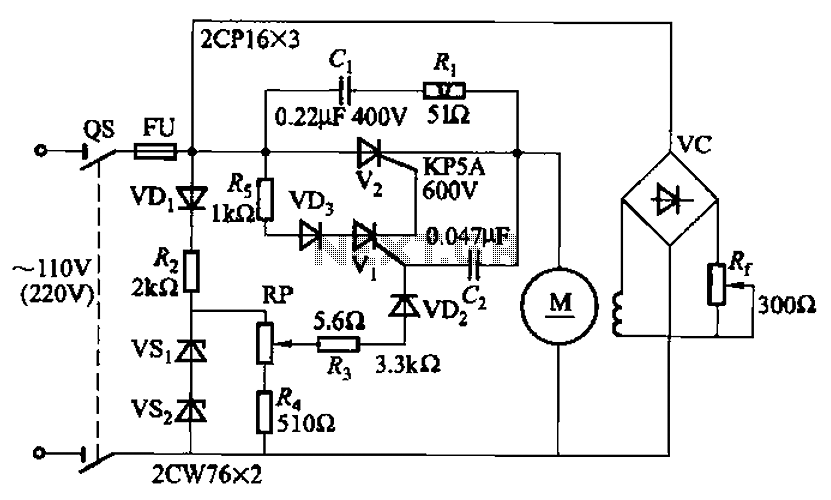
A 100W resistance-triggered motor control circuit designed for arc welding machines. It features an adjustment potentiometer (Rr) that can modify the DC motor excitation current. Additionally, a regulator (RP) is included to adjust the DC motor armature voltage, enabling...
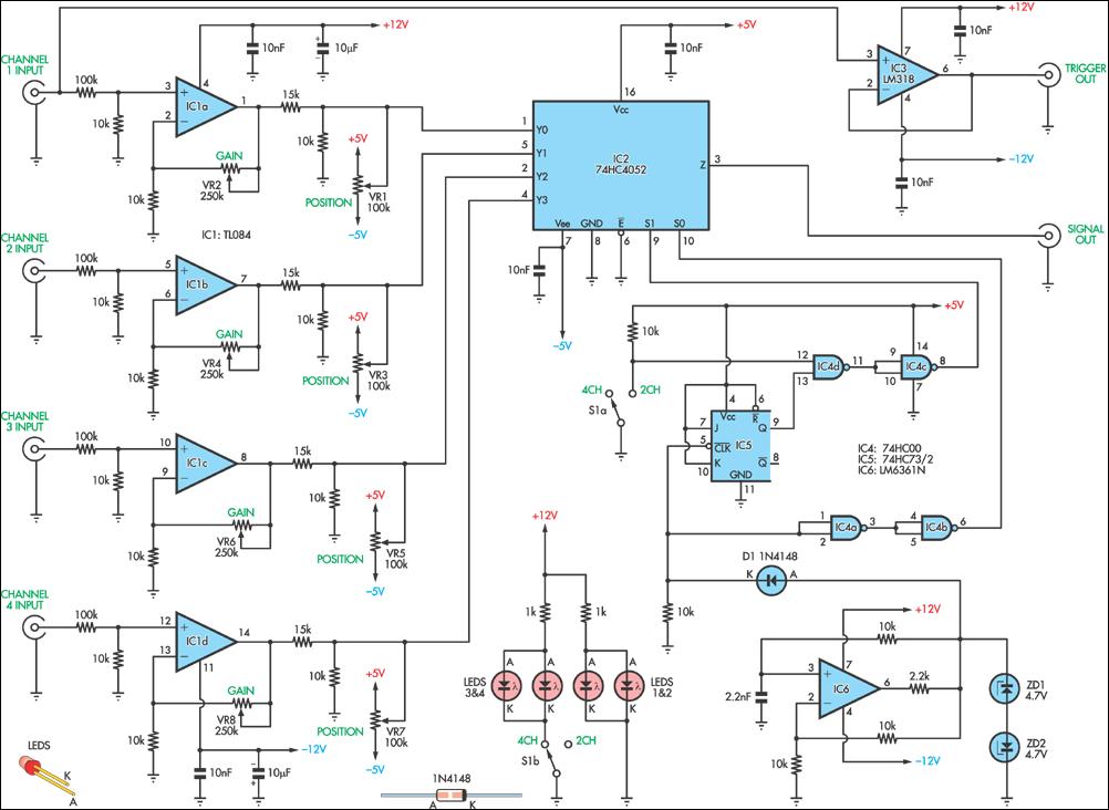
This circuit allows for the simultaneous display of four signals using a single channel of an oscilloscope. It sequentially switches each input to the output with some signal processing in between. It is designed for low-frequency signal measurements and...
Probably the best advantage is its very small size and the fact that it can run off the power supply of the circuit being tested. Although it has a low frequency range, it can still be used for most...
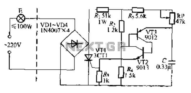
The circuit is a one-way ordinary transistor-triggered dimmer light circuit. It uses a complementary amplifier configuration with transistors VT2 and VT3 to form the thyristor trigger circuit for VT1. The circuit operates with a 220V alternating current through the...
Simple homemade oscilloscopes are not difficult to design and build. Various designs dating back to the 1930s have been studied, leading to the development of a simple oscilloscope that electronics hobbyists can construct using readily available parts today. The...