
100W resistance triggered doer control circuit

This circuit is primarily utilized in arc welding applications, where precise control over the motor's operation is essential for effective welding processes. The resistance-triggered design allows for straightforward implementation, making it an ideal choice for basic welding machine setups.
The adjustment potentiometer (Rr) plays a crucial role in controlling the excitation current of the DC motor. By varying the resistance, the user can influence the magnetic field strength generated within the motor, thereby affecting its torque and overall performance. This capability is vital for adapting the welding process to different materials and thicknesses.
The regulator (RP) is responsible for controlling the armature voltage supplied to the DC motor. Adjusting this voltage directly impacts the motor's speed, allowing for fine-tuning during operation. This feature is particularly useful in welding applications where different speeds may be required depending on the welding technique or material being used.
Overall, this circuit design emphasizes simplicity and functionality, making it accessible for those involved in welding machine construction or modification. Proper implementation of the adjustment potentiometer and regulator will enable users to achieve optimal performance from their arc welding machines.100W resistance triggered doer control circuit It is dragging the arc welding machine control circuit of the most simple kind. Adjustment potentiometer Rr, can change the DC mo tor excitation current. Regulator RP, can change the DC motor armature voltage, to achieve speed control purposes.
Related Circuits
The following circuit illustrates the use of a 555 integrated circuit (IC) for an infrared (IR) remote control extender circuit. Features include support for 850 nm and 950 nm signal wavelengths, along with the capability to generate control pulses. The...
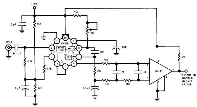
A simple Frequency Shift Keying (FSK) demodulator for 2025 Hz and 2225 Hz can be designed using the LM565, a general-purpose phase-locked loop integrated circuit. This IC includes a stable, highly linear voltage-controlled oscillator that provides low distortion FM...
Chris from PyroElectro.com has an informative article detailing a do-it-yourself radar system constructed using the PIC18F452 microcontroller. This project is an excellent hobbyist endeavor, although the schematic design is quite complex. The system integrates three primary components to form...

This temperature-controlled relay circuit is a simple yet highly accurate thermal control circuit that can be used in applications requiring automatic temperature regulation. The temperature-controlled relay circuit operates by monitoring the ambient temperature and activating or deactivating a connected load...
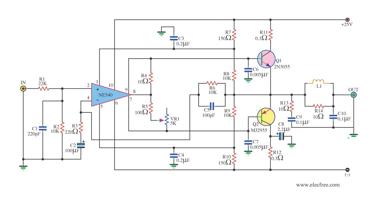
When the power supply reaches the circuit and the input signal is applied, the sound signal is processed through capacitor C1 and resistor R1 for signal coupling and noise reduction. The modified signal then reaches pin 3 (non-inverting) of...
This is a simple, programmable, autonomous and extensible LED matrix with the possibility of being controlled by a computer using a RS232 connection. Its basic modules are the Controller Board, the I/O Port expander boards and the LED matrix...