
Dual voltage power supply 12 volts

The described circuit functions as a dual voltage regulated power supply, providing three output voltages: +12V, -12V, and 0V. It employs two linear voltage regulators, the LM7812 for the positive voltage output and the LM7912 for the negative voltage output.
To begin, the circuit requires an 18V center-tapped transformer (18VCT) with a current rating of at least 1A. The center tap serves as the ground reference, while the two secondary windings provide the necessary voltages for the regulators. The AC voltage from the transformer is first rectified using a bridge rectifier, which converts the AC voltage to pulsating DC.
After rectification, filtering capacitors are utilized to smooth the pulsating DC voltage, ensuring that the voltage presented to the regulators is stable. Typically, a large electrolytic capacitor is placed at the output of the rectifier to minimize voltage ripple.
The LM7812 regulator is connected to the positive side of the rectified output, while the LM7912 is connected to the negative side. It is crucial to note that the input and ground connections are reversed between the two regulators. The LM7812 requires the input voltage to be connected to the output of the rectifier, while the ground pin should be connected to the center tap of the transformer. Conversely, the LM7912 has its input connected to the negative side of the rectified output, and its ground pin is also connected to the center tap.
Each regulator outputs a stable voltage of +12V and -12V, respectively. Additional decoupling capacitors are recommended at the output of each regulator to further enhance stability and transient response. These capacitors are typically in the range of 0.1µF to 10µF and help filter out high-frequency noise.
This power supply circuit is commonly used in various applications where dual polarity power is required, such as operational amplifier circuits, analog signal processing, and audio equipment. Proper thermal management should also be considered, as the regulators may dissipate significant heat depending on the load. Heat sinks may be necessary to ensure the regulators operate within safe temperature limits.This circuit is a dual voltage regulated power supply, +12, -12, 0 volt. It uses the 7812 and 7912 regulators. You need a 18VCT, 1A transformer at input. Caution: Input / Ground are reversed between the 7812 and 7912. 🔗 External reference
Related Circuits

This integrated circuit (IC) chip is specifically designed for power boosting applications in automobiles. It features self-protection mechanisms against short circuits and thermal issues. In the bridge configuration depicted, it can deliver 20 watts of power to a 2-ohm...
An alternative approach to utilizing operational amplifiers (op-amps) for power supply regulation is presented. This method necessitates an additional winding on the power transformer to provide the op-amps with a bipolar voltage of +/- 8 volts. The negative voltage...
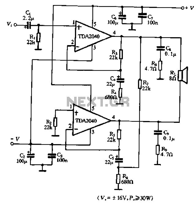
The TDA2040 is a power audio amplifier with a wider operating voltage range compared to the TDA2030, ranging from 4V to 20V. It can deliver an output power of 18W at a load of 4 ohms when supplied with...

Schematic diagram for a dual polarity single channel input voltage to oscillating frequency control. The circuit can be divided into five parts. The reference voltage is established using a TL431 and a 1.2k resistor, functioning as a 2.5V regulator....
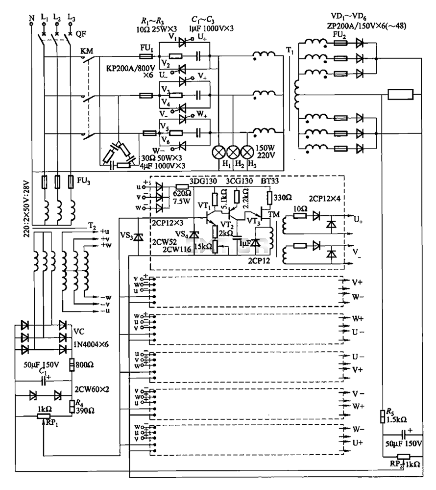
A three-phase thyristor power regulator circuit designed for plating applications, capable of handling currents from 1200A to 6000A at a voltage of 10V. The circuit comprises a main circuit, a trigger circuit, synchronous power components, and a voltage negative...
The circuit comprises two sections: charger power supply and LED driver. The charger power supply section is built around a 3-terminal adjustable regulator (IC1) LM317, while the LED driver section is built around transistor BD140 (T2). In the charger...