
1200 to 6000A-10V three-phase thyristor power regulator circuit plating

The three-phase thyristor power regulator circuit is engineered for industrial plating processes where precise control of current and voltage is critical. The main circuit is responsible for converting the input AC power into a regulated DC output, which is essential for electroplating applications. The thyristors serve as the primary switching elements, allowing for efficient control of the power delivered to the load.
The trigger circuit plays a vital role in controlling the firing angle of the thyristors, thereby regulating the output voltage and current. By adjusting the firing angle, the circuit can finely tune the output to meet specific plating requirements. The synchronous power components ensure that the thyristors operate in harmony with the AC input, maintaining system stability and performance.
Voltage negative feedback is implemented to monitor the output voltage continuously. This feedback loop enables the circuit to adjust the firing angle of the thyristors automatically, ensuring that the output voltage remains within desired limits despite variations in load or input conditions. Protection circuits are integrated to safeguard the system against overcurrent, overvoltage, and thermal overload conditions, enhancing the reliability and longevity of the power regulator.
For applications requiring higher current outputs, the circuit allows for the parallel configuration of rectifier diodes. This flexibility means that as demand increases, additional diodes can be added without necessitating a complete redesign of the circuit. The use of a master adjustment potentiometer (RPi) provides operators with the ability to fine-tune the cell voltage, accommodating various plating solutions and operational conditions.
Overall, this thyristor power regulator circuit is a robust solution for high-current applications, combining efficient power conversion with precise control mechanisms to meet the demanding requirements of industrial plating processes.1200 to 6000A-10V three-phase thyristor power regulator circuit plating It consists of a main circuit, trigger circuit, synchronous power, voltage negative feedback circuit and protection circuits and other components. The basic circuit configuration is similar to FIG. This circuit uses when six rectifier diodes 200A can output 1200A, higher current output requirements, can be a plurality of rectifying diodes in parallel, such as the use of 48 200A rectifier diodes, output 6000A (circuit elements other parameters unchanged). Master adjust potentiometer RPi, you can change the size of the cell voltage.
Related Circuits
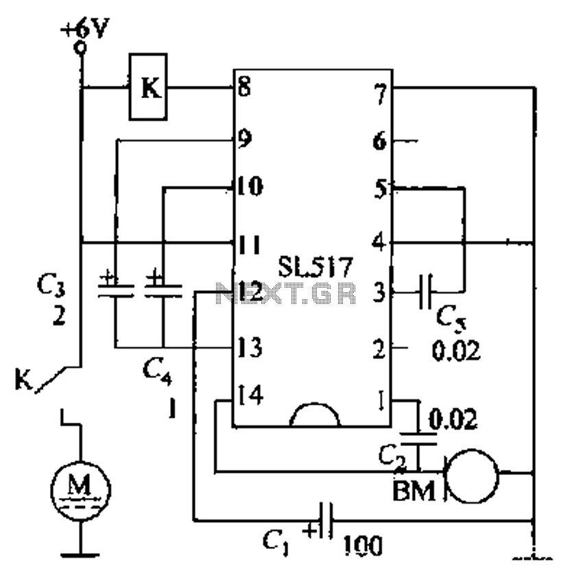
Electric cars utilize a voice circuit principle, where sound signals are captured by a microphone (BM) and processed. The signal is then coupled through a capacitor to an integrated circuit (IC), which includes an internal amplifier that boosts the...
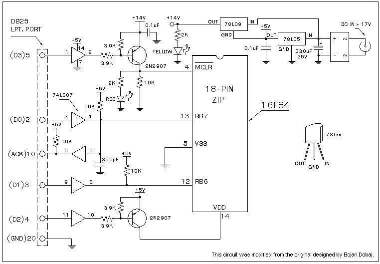
A universal Windows-based software designed to work with any serial programmers for the PIC16F84, known as WPicProg16 V1.20. It is recommended to build this programmer before starting various interesting projects with the F84. Some PIC programmers support in-circuit programming,...
This circuit is a simple form of the commercial UPS, the circuit provides a constant regulated 5 Volt output and an unregulated 12 Volt supply. In the event of electrical supply line failure the battery takes over, with no...
The i-TRIXX circuit is designed to prevent issues for individuals traveling in a caravan. It provides an early warning system through an illuminated LED, alerting users when the battery charge is low, thereby preventing the inconvenience of being unable...
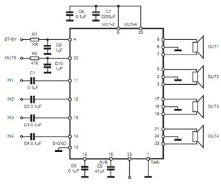
The TDA7383 features a fully complementary PNP/NPN output configuration, enabling a rail-to-rail output voltage swing without the need for bootstrap capacitors. This design significantly reduces the component count, allowing for compact assemblies. An integrated clipping detector facilitates gain compression...
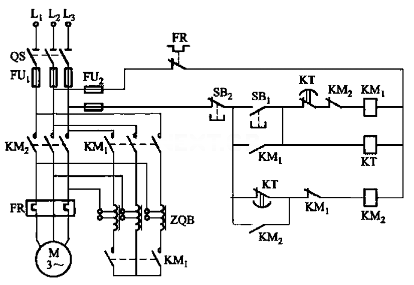
The circuit depicted in Figure 3-49 illustrates an autotransformer that is controlled by a time relay (KT). The delay time set by the KT relay corresponds to the motor's startup duration. The circuit utilizes an autotransformer, which is a type...