
dynamic mic mid boost schematic

The dynamic microphone mid boost and bass rolloff circuit is designed to enhance the audio signal captured by a dynamic microphone, particularly in applications where vocal clarity and presence are essential. The schematic typically includes components such as resistors, capacitors, and operational amplifiers to achieve the desired frequency response.
In this circuit, the mid boost is accomplished by utilizing a band-pass filter configuration that amplifies frequencies in the midrange, typically between 1 kHz and 3 kHz. This is crucial for ensuring that vocals are more pronounced in a mix, making them stand out during live performances or recordings. The selection of resistor and capacitor values will determine the exact frequency range that is boosted.
The bass rolloff feature is implemented to reduce lower frequencies that may muddy the mix or cause feedback issues. A high-pass filter is employed for this purpose, allowing higher frequencies to pass while attenuating those below a certain cutoff frequency. The cutoff frequency can be adjusted by changing the values of the capacitors and resistors in the circuit, allowing for customization based on the specific microphone and application.
Overall, this dynamic microphone mid boost and bass rolloff schematic serves as an effective tool for audio engineers and musicians seeking to optimize the performance of dynamic microphones in various sound environments. Proper implementation of this circuit can significantly enhance the quality of audio output, leading to clearer and more professional sound reproduction.Dynamic Mic Mid Boost And Bass Rolloff Schematic Photo: dynamic mic mid boost and bass rolloff schematic. taken from documentation of a known working po .. 🔗 External reference
Related Circuits
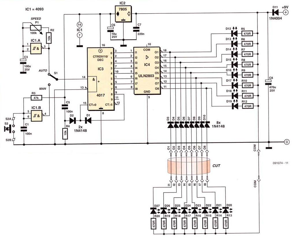
This network wiring tester consists of two components: a transmitter unit, which is powered and installed at the network's starting point, and a passive receiver unit that can be moved from socket to socket. Both units contain eight LEDs,...
This chapter includes circuit diagrams for various power supplies designed for pulsed solid-state lasers. It features units that are compatible with the widely used Hughes ruby and YAG rangefinder laser assemblies, one utilizing the flash from a disposable pocket...
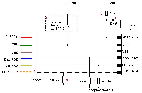
Microchip does not recommend any specific circuit for In-Circuit Serial Programming (ICSP). Various diagrams exist for different tools, such as Pro Mate and PICKit2, which feature similar circuitry with minor variations. Some schematics may suggest resistor values that are...
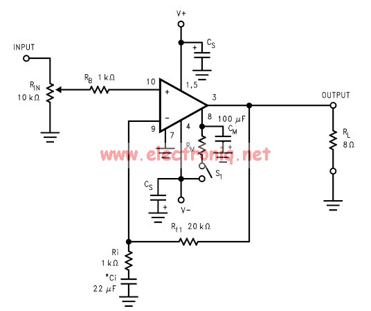
The LM3886 amplifier electronic circuit project is designed to deliver 68W of continuous average power into a 4-ohm load and 38W into an 8-ohm load with a total harmonic distortion plus noise (THD+N) of 0.1% across the frequency range...
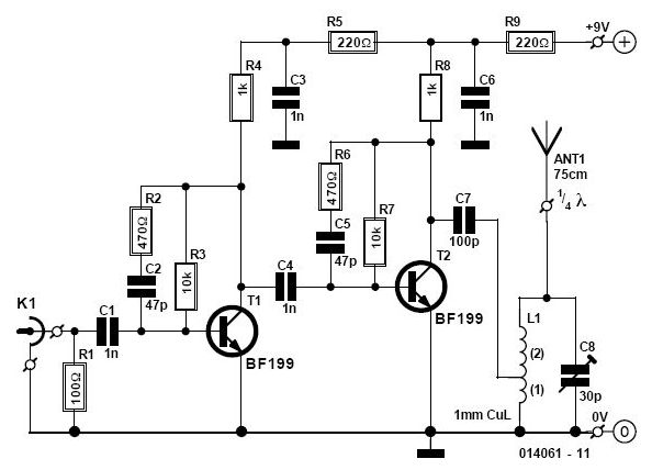
This circuit enables the use of a portable VHF FM radio to receive audio from stations that exclusively broadcast on the local cable network. This circuit operates by modulating the audio signals from the local cable network onto a carrier...
This is a simple microphone preamplifier circuit which you can use between your dynamic microphone and any equipment designed to work with an electret microphone (2 wire connection to electret capsule). This amplifier amplifies the low level signal to...