
Dynamic Testing of High-Speed ADCs Part 2

This article provides essential guidelines for testing high-speed ADCs, focusing on the dynamic performance metrics crucial for evaluating their operational efficiency. Key parameters such as signal-to-noise ratio (SNR), total harmonic distortion (THD), and spurious-free dynamic range (SFDR) are discussed in detail. The recommended test conditions include specific configurations for input signals, sampling rates, and environmental factors that may influence measurement accuracy.
To achieve reliable results, the article emphasizes the importance of using calibrated test equipment and appropriate signal sources. It suggests employing high-quality oscilloscopes and signal generators that can operate at the ADC's specified frequency range. Additionally, proper grounding and shielding techniques are recommended to minimize noise and interference during the testing process.
The article also addresses the setup of the test environment, highlighting the need for stable power supplies and controlled temperature conditions to ensure consistent performance across multiple measurements. By following these guidelines, engineers can obtain a comprehensive understanding of the dynamic performance of high-speed ADCs, facilitating better design and optimization of electronic systems that incorporate these components.The following article is a follow-up application note to `Defining and Testing Dynamic Parameters in High-Speed ADCs, Part 1`. It details test conditions and setup recommendations to efficiently measure the dynamic performance parameters of high-spee..
🔗 External reference
Related Circuits
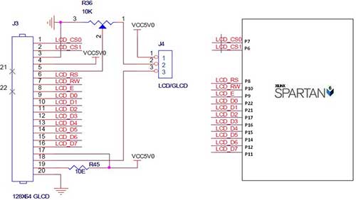
The Spartan-6 board features a 2x16 LCD, as illustrated in the accompanying figure. This 2x16 character LCD interface card supports both 4-bit and 8-bit modes, and it includes a facility for contrast adjustment via a trim potentiometer. In the...
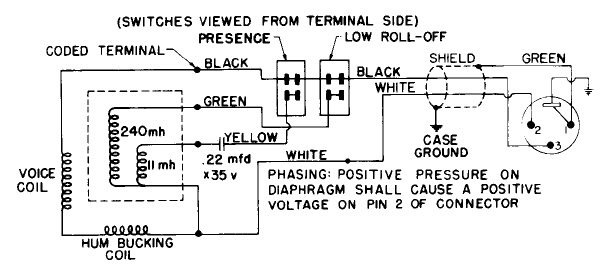
Dynamic microphone mid boost and bass rolloff schematic. This schematic is derived from the documentation of a known working prototype. The dynamic microphone mid boost and bass rolloff circuit is designed to enhance the audio signal captured by a dynamic...
The circuit is a modified Colpitts oscillator, tuned with MV209 varactor diodes. The resonating inductor and the drain choke are selected by a rotary switch. 1N5711 Schottky diode, D, clamps the maximum positive voltage on the gate of oscillator...
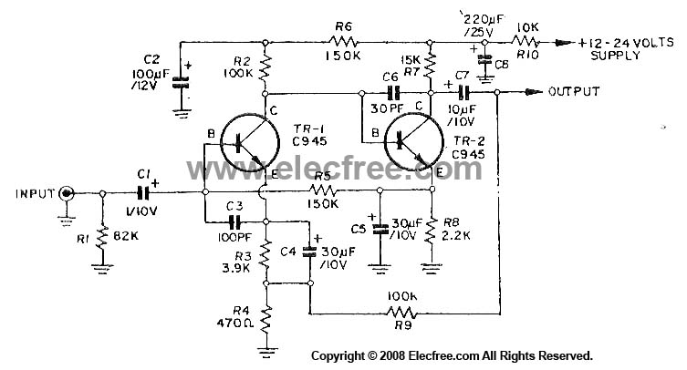
This circuit utilizes three transistors (2SC945, 2C1815, or 2SC828) as the primary components, functioning as a typical low-noise transistor amplifier. It offers a gain of approximately 200 to 300 times and has a frequency response ranging from 50Hz to...
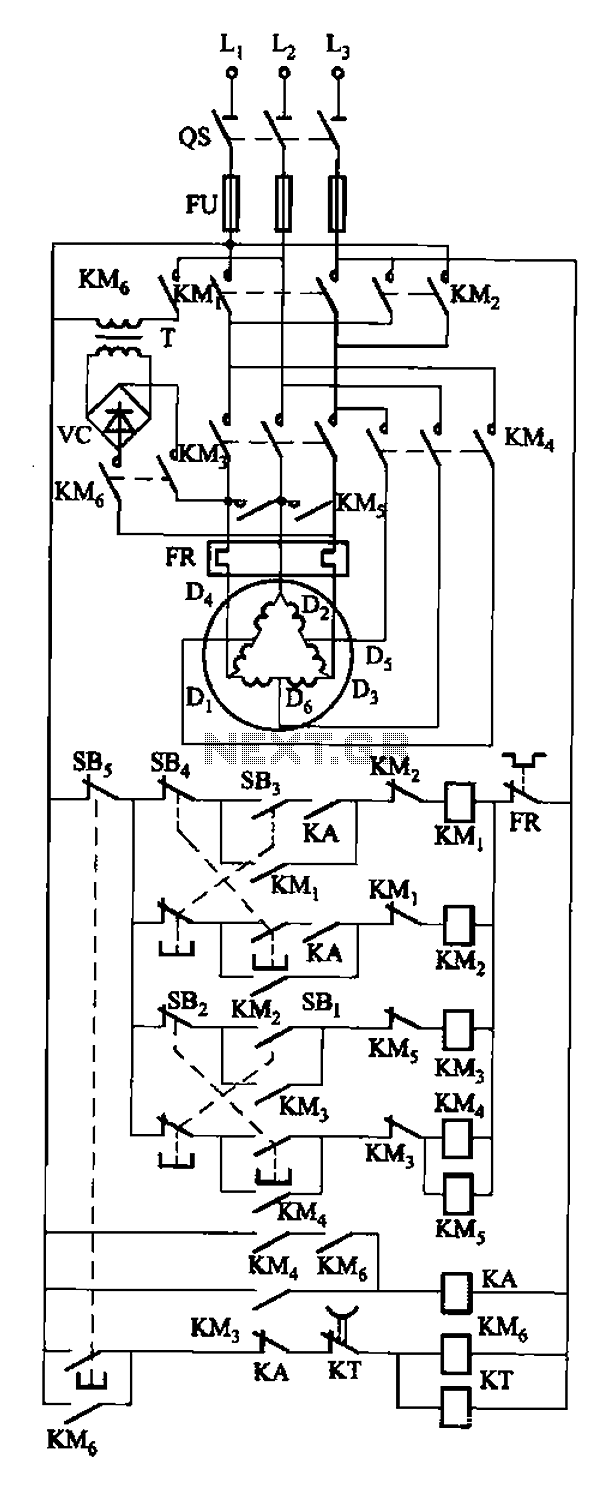
The circuit depicted in Figure 3-108 includes various control buttons: SB3 for the forward button, SI for the reverse button, SBi as the low start button, SB2 for the speed start button, and SBs for the stop button. KMs...
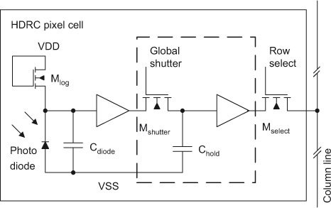
The initial section of this document outlines the high dynamic range CMOS (HDRC) imager, a specialized type of CMOS image sensor characterized by its logarithmic response. The significant capabilities of high dynamic range (HDR) image acquisition are explained through...