
Earth Fault Indicator

The proposed circuit serves as a safety mechanism that monitors the integrity of the earth connection in electrical appliances. The design utilizes a diode for rectification, ensuring that the circuit operates efficiently with minimal power requirements. The inclusion of a capacitor allows for the accumulation of voltage, which is critical for triggering the neon indicator. The neon light's flashing serves as a visual alert, indicating a potential safety hazard due to the disconnection of the earth wire.
When implementing this circuit, careful attention must be paid to the component ratings, particularly the voltage rating of the capacitor and the power rating of the resistor. These components must be chosen to withstand the operational conditions while ensuring long-term reliability. The design's simplicity is a significant advantage, as it can be easily integrated into existing appliances without extensive modifications.
Moreover, the installation process should emphasize safety and clarity in wiring connections to prevent accidental misconfiguration, which could lead to circuit failure or safety risks. This project highlights the importance of proactive safety measures in electrical engineering, particularly in environments where moisture and corrosion are prevalent. Overall, this circuit not only enhances the safety of electrical devices but also promotes awareness of the potential risks associated with faulty earth connections.The security of many electrical devices depends today on the availability of an earthed mains outlet. We should remember that these are connected to the frame or to the metal housing of the equipment and so it routes to the protective earth (PE) connections.
In this setup, mains voltage, however small, will cause the differential circuit breaker t o trip. The circuit breaker is part of any modern electrical installation. This type of security device may however become defective due to common corrosion as we have seen many times on various older household devices, as well as on construction sites. Actually, since these devices are frequently in wet conditions, the screw and/or lug used to connect the earth wire to the device frame corrodes gradually and ends up breaking or causing a faulty contact.
The remedy is then worse than the problem because the user, thinking that he/she is protected by earth, does not take special precautions and risks his/her life. However, all that`s needed is an extremely simple system to automatically detect any break in the earth connection; so simple that we ask ourselves why it is not already included as part of all factory production for appliances that carry any such risk, as we have discussed above.
We propose it as a project for you to build using this schematic. The live wire (L) of the mains power supply is connected to diode D1 which ensures simple half-wave rectification which is sufficient for our use. The current which is available is limited to a very low value by resistor R2. If the appliance earth connection to which our circuit is installed is efficient, this current is directed to earth via resistor R1 and the rest of the circuit is inactive due to insufficient power.
If the earth connection is disconnected, the current supplied by D1 and R2 charges up capacitor C1. When the voltage at the terminals of the capacitor reaches about 60 volts, neon indicator light La1 is turned on and emits a flashing light which discharges capacitor C1 at the same time. This phenomenon is reproduced indefinitely as long as the earth connection has not been restored, and the neon light continues to flash to attract attention in case of danger.
Building the project is not particularly difficult but, since it is a project aimed at human safety, we must take the maximum of precautions concerning the choice of components utilised. Therefore, C1 must have an operating voltage of at least 160 volts while R2 must be a 0. 5-watt resistor, not for reasons of power dissipation, but in order to maintain the voltage. The neon light can be any type, possibly used, or it may be part of an indicator light to make it easier to attach to the protected appliance.
In the second case, we must obviously get rid of its series resistor which would prevent proper operation here. During installation of the circuit in the appliance to be protected, we should also clearly mark Live (L) and Neutral (N) (for example, seek Live with a simple screwdriver) because inverting these two wires at this point will disable proper operation.
The final point, which is self-evident considering the principle used here: the earth connection for our setup must be hooked up to the frame of the appliance to be protected at a different point than where the normal earth wire is connected. 🔗 External reference
Related Circuits
This design integrates power-on and low-battery indication features, capable of operating with any battery voltage up to 15V. It has a very low current drain of 2mA or less and is cost-effective, priced under $3.50 with new components. When...
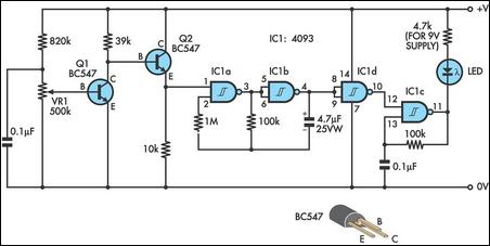
An audible field strength indicator (AFSI) allows users to listen to variations in radio signal strength, aiding in the detection of concealed antennas. This design utilizes inexpensive and readily available components, integrating a sensitive amplified field strength detection circuit...
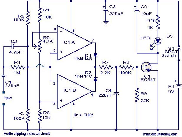
This circuit is designed to detect clipping in a specific waveform. Clipping occurs when the amplitude of a waveform decreases before reaching its expected limit. The circuit activates an LED as an indication that the tested signal is experiencing...
12V Battery Charge Nominal Discharge (Low) Indicator Circuit. This circuit monitors car battery voltage and provides an indication of nominal levels. The 12V Battery Charge Nominal Discharge Indicator Circuit is designed to monitor the voltage levels of a car battery...

This circuit utilizes standard components to indicate the fuse status of mains-powered equipment while ensuring electrical isolation from the mains supply. A standard miniature low-power mains transformer (for example, with an output of approximately 6 V at 1.5 VA)...
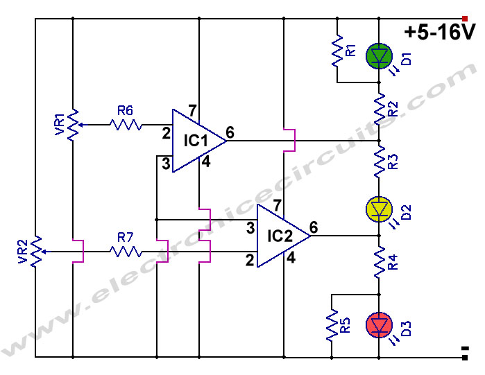
This is a battery tester circuit. This circuit is used to indicate whether the level of a battery voltage is normal, under-voltage, or over-voltage. The battery tester circuit is designed to assess the voltage level of a battery and provide...