
Easily Tuned Sine Wave Oscillators

The circuit described utilizes a combination of filtering and clipping techniques to generate a stable sine wave output from a square wave input. The design focuses on achieving low distortion levels while maintaining the ability to tune the frequency across a wide range. The operational amplifier serves as a critical component, acting as a tuned circuit that processes the square wave signal to produce the desired sine wave output.
The oscillator circuit operates by first generating a square wave, which is then clipped to form a sine wave. The clipping process not only shapes the wave but also stabilizes the amplitude, which is crucial for consistent performance. The use of Zener diodes ensures that the amplitude remains stable, even with variations in the input signal or environmental conditions.
The tuning mechanism is facilitated by resistors and capacitors, allowing for fine adjustments to the frequency of oscillation. This is particularly advantageous in applications where precise frequency control is necessary. The circuit's self-starting capability is an essential feature, ensuring that it can initiate operation without external triggering.
In terms of performance, the oscillator is capable of producing outputs with distortion levels ranging from 0.75% to 2%, depending on the tuning settings. This level of distortion is acceptable for many applications, especially when compared to traditional square wave oscillators, which can introduce significant harmonic content.
The design also emphasizes the importance of component quality. Using high-grade resistors and capacitors minimizes noise and improves overall circuit performance. Additionally, the shielding of sensitive components from interference is a critical consideration in maintaining signal integrity.
Overall, this circuit design represents a robust solution for generating sine waves with low distortion, suitable for a variety of electronic applications. The careful selection of components, along with innovative circuit techniques, ensures reliable and high-quality performance across a wide frequency range.One approach to generating sine waves is to filter a square If a lower distortion oscillator is needed the circuit in Figure wave This leaves only the sine wave fundamental as the 2 can be used Instead of driving the tuned circuit with a output Since a square wave is easily amplitude stabilized by square wave a symmetrically clipped sine wave is used clipping the sine wave output is also amplitude stabilized A. The clipped sine wave of course has less distortion than a clipping oscillator eliminates the problems encountered with square wave and yields a low distortion output when filtered agc stabilized oscillators such as those using Wein bridges This circuit is not as tolerant of component values as the Additionally since there is no slow agc loop the oscillator one shown in Figure 1 To insure oscillation it is necessary starts quickly and reaches final amplitude within a few cy- that sufficient signal is applied to the zeners for clipping to cles occur Clipping about 20% of the sine wave is usually a good value The level of clipping must be high enough to C1 e C2 Frequency Adjust Amplitude Adjust 1 F0 j 2 q C 1 0R 3 R 1 TL H 8466 1 FIGURE 1 Easily Tuned Sine Wave Oscillator The circuit in Figure 1 will provide both a sine and square insure oscillation over the entire tuning range If the clipping wave output for frequencies from below 20 Hz to above 20 is too small it is possible for the circuit to cease oscillation kHz The frequency of oscillation is easily tuned by varying a due to tuning component aging or temperature changes single resistor This is a considerable advantage over Wein Higher clipping levels increase distortion As with the circuit bridge circuits where two elements must be tuned simulta- in Figure 1 this circuit is self-starting neously to change frequency Also the output amplitude is Table I shows the component values for the various fre- relatively stable when the frequency is changed quency ranges Distortion from the circuit in Figure 1 ranges An operational amplifier is used as a tuned circuit driven by between 0 75% and 2% depending on the setting of R3 square wave from a voltage comparator Frequency is con- Although greater tuning range can be accomplished by in- trolled by R1 R2 C1 C2 and R3 with R3 used for tuning creasing the size of R3 beyond 1 kX distortion becomes Tuning the filter does not affect its gain or bandwidth so the excessive Decreasing R3 lower than 50X can make the output amplitude does not change with frequency A com- filter oscillate by itself The circuit in Figure 2 varies between parator is fed with the sine wave output to obtain a square 0 2% and 0 4% distortion for 20% clipping wave The square wave is then fed back to the input of the About 20 kHz is the highest usable frequency for these os- tuned circuit to cause oscillation Zener diode D1 stabilizes cillators At higher frequencies the tuned circuit is incapable the amplitude of the square wave fed back to the filter input of providing the high Q bandpass characteristic needed to Starting is insured by R6 and C5 which provide dc negative filter the input into a clean sine wave The low frequency LB-16 feedback around the comparator This keeps the compara- end of oscillation is not limited except by capacitor size tor in the active region C1995 National Semiconductor Corporation TL H 8466 RRD-B30M115 Printed in U S A C1 e C2 Frequency Adjust Clipping Level Adjust 1 F0 j 2 q C 1 0R 3 R 1 TL H 8466 2 FIGURE 2 Low Distortion Sine Wave Oscillator TABLE I capacitance causing spikes on the output Therefore the output of the comparator with the associated circuitry Min Max C1 C2 should be shielded from the inputs of the op amp Frequency Frequency Component choice is also important Good quality resistors 0 47 mF 18 Hz 80 Hz and capacitors must be used to i 🔗 External reference
Related Circuits
One unit is in good condition, manufactured in 1979, and is capable of generating sine, triangle, and square waveforms. This unit is retained and utilized as the primary function generator for testing purposes at the main office location. The...
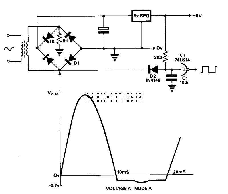
A line frequency square wave with a 1:1 duty cycle can be generated using only three components and a buffer from the power supply. During the alternate half-cycle, point A is clamped to approximately -0.7 V by diode D1...
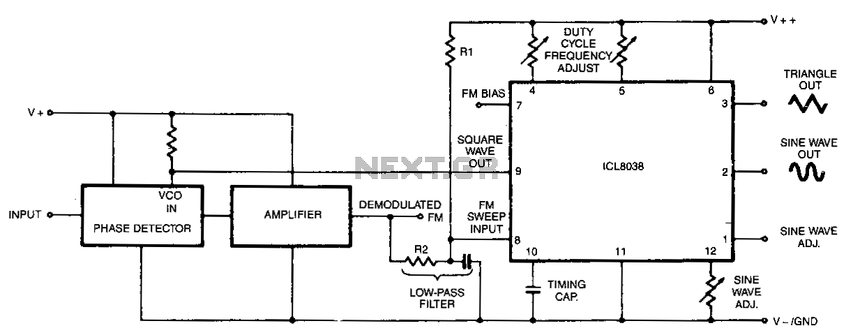
In this circuit, a waveform generator is used as a stable voltage-controlled oscillator (VCO) in a Phase-Locked Loop (PLL). The circuit utilizes a waveform generator configured as a voltage-controlled oscillator (VCO), which is a critical component in the design of...
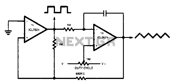
The output range varies precisely from rail to rail, making the frequency and duty cycle nearly independent of power supply variations. The circuit in question is designed to operate with a wide output range that spans from the minimum to...
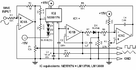
If a triangle wave signal or a square wave is required but only a sine wave generator is available, this converter can be utilized to simplify the process. The circuit consists of two integrated circuits (ICs): an LM13700 and...
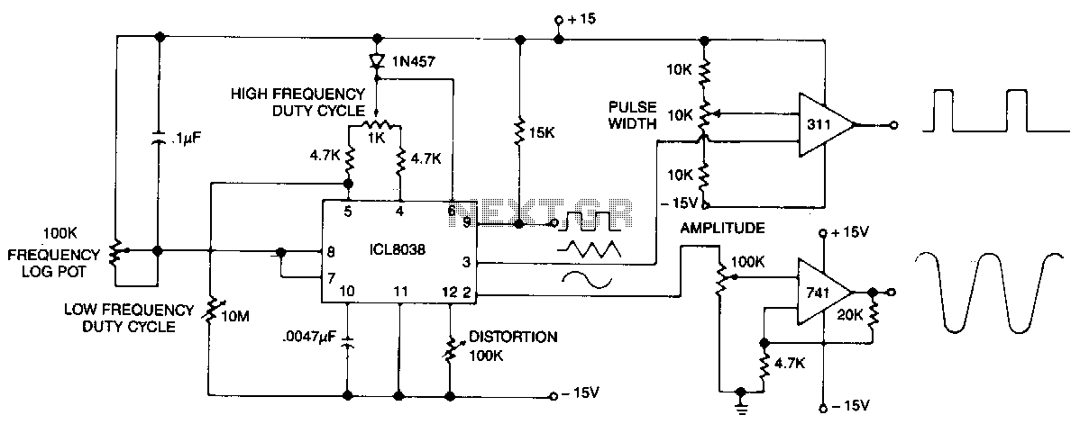
This circuit generates sinusoidal, square, and triangle waveforms simultaneously. The frequency can be set to a specific value or varied as indicated. An operational amplifier can be added for enhanced drive capability and simplified amplitude adjustment. Additionally, a simple...