
Easy and low cost IRF540/9540 amp

The amplifier design utilizing 9240/240 Mosfets indicates a focus on high-efficiency and high-performance amplification. The 9240 and 240 are both N-channel and P-channel MOSFETs, respectively, commonly used in audio amplification applications due to their low on-resistance and high current handling capabilities.
In a typical configuration, the amplifier could be designed using a complementary push-pull circuit topology, where the 9240 and 240 MOSFETs work together to amplify the audio signal. The circuit would include a differential input stage to ensure low distortion and high fidelity. Feedback mechanisms could be integrated to stabilize the gain and reduce any potential crossover distortion, which is crucial in audio applications.
Power supply considerations are essential for this kind of amplifier. A dual power supply design, providing both positive and negative voltages, would be ideal to ensure that the MOSFETs operate within their optimal range. Additional components such as filter capacitors would be necessary to smooth out the power supply and prevent any ripple from affecting the audio output.
Thermal management is another critical aspect of the design, as MOSFETs can generate significant heat during operation. Proper heat sinking and possibly active cooling solutions should be implemented to maintain safe operating temperatures and ensure reliability over long periods of use.
Overall, the amplifier design utilizing 9240/240 MOSFETs has the potential to deliver high-quality audio performance, and further refinements could enhance its capabilities for practical listening applications.Hi all, I completed my first amp a few months ago. It was more a test than really something to listen to. It used the 9240/240 Mosfets. Now I want to.. 🔗 External reference
Related Circuits
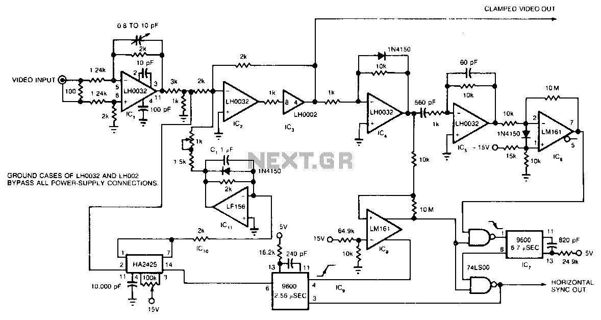
The circuit utilizes a track-and-hold amplifier in a closed-loop configuration to clamp the back-porch voltage of a standard video waveform to 0 V. The outputs of the circuit include a clamped composite video signal and a TTL-level horizontal blanking...
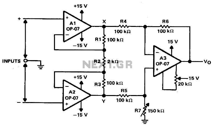
Operational amplifiers A1 and A2 are connected in a non-inverting configuration to form amplifier A3. The operational amplifier A3 can be classified as a subtractor circuit that converts the differential signal between the floating points X and Y into...
High-quality, discrete component design for input and tone control modules to complement the 60-watt MOSFET audio amplifier with a high-quality preamplifier design. The circuit design focuses on creating a high-fidelity audio preamplifier that enhances the performance of a 60-watt MOSFET...
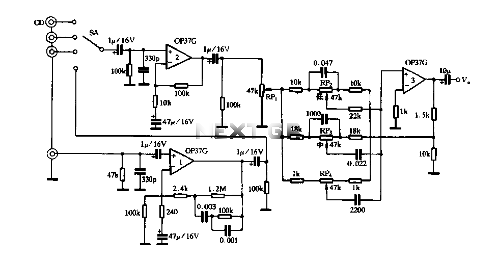
Figure 3 illustrates a circuit featuring the OP37, which is a multi-preamplifier configuration. The OP37 offers superior performance compared to the NE5534 integrated operational amplifier, as indicated in Table 3-3, which contrasts the parameters of both circuits. The table...
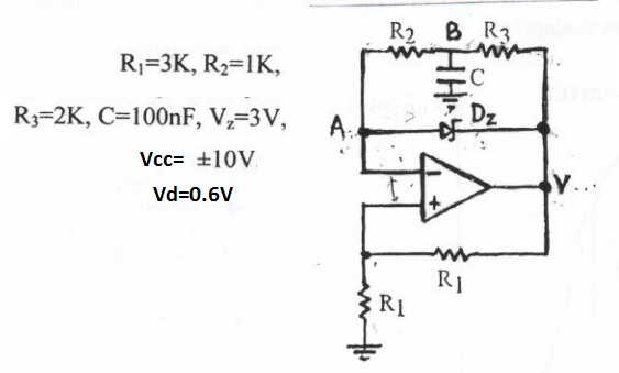
This circuit appears to be a Schmitt trigger oscillator. Based on the configuration of the resistors and capacitor, it is likely functioning as a sawtooth wave generator, with resistors R2 and R3 influencing the slope of the rising and...
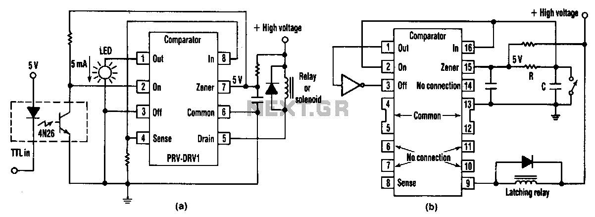
At half brightness, the lamp current is pulsed on and off by the voltage developed across the resistor and capacitor at the current-sense output. The current-sense output detects the lamp current. A basic pulse-width modulation (PWM) lamp-brightness control circuit...