
oscillator circuit with opamp and zener diode

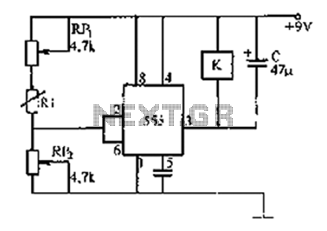
The circuit utilizes a Schmitt trigger, which is known for its ability to provide hysteresis in the input signal, allowing for clean transitions between high and low states. The sawtooth wave generator aspect is achieved through the charging and discharging of a capacitor, which is influenced by the resistors R2 and R3. The values of these resistors determine the rate at which the capacitor charges and discharges, thereby affecting the frequency and duty cycle of the output waveform.
The Zener diode plays a crucial role in this configuration. By clamping the voltage at a specified level, it ensures that the output does not exceed a certain amplitude, thereby protecting downstream components from potential damage due to overvoltage. If the Zener diode is indeed truncating the waveform, it modifies the output from a pure sawtooth to a trapezoidal shape, which may be beneficial in applications requiring a more controlled voltage profile.
In practical applications, this type of oscillator can be used in signal generation, timing circuits, and waveform shaping. The precise control over the output waveform characteristics makes it suitable for various electronic applications, including audio synthesis and modulation. The design's simplicity and effectiveness make it an excellent choice for engineers looking to implement a reliable waveform generator in their projects.Looks like a schmitt trigger oscillator. By the way the resistors and capacitor are used it is probably a saw-tooth wave generator with R2 & R3 determining the slope of the rising and trailing edges. The zener helps control the amplitude between 0 to 3V OR maybe it chops off the tops of the sawtooth wave thereby creating an output that has a trapezoidal waveform.
🔗 External reference
Related Circuits
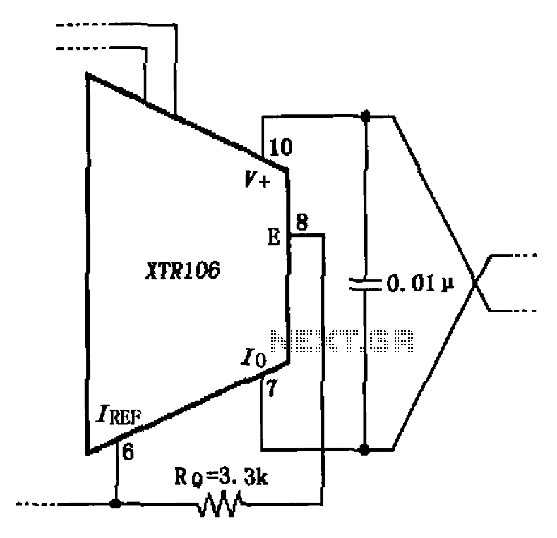
The circuit has been simplified due to the cancellation of an external transistor. The connection between the emitter terminals of the original external transistor and a 3.3k resistor will be removed, as this change has led to a decrease...
The motor protection circuit consists of a power supply circuit, a current detection circuit, and a protection control circuit, as depicted in the accompanying diagram. The power circuit includes a power transformer (T), a rectifier diode (VD4), filter capacitors...

CO2 gas shielded arc welding power supply electromagnetic vibration circuit is commonly used in farm machinery repair. The maximum arc voltage is 30V, with a maximum welding current of 300A. The wire feed speed ranges from 0 to 12...
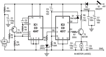
The following circuit illustrates an Infrared Toy Car Motor Controller Circuit Diagram. This circuit is based on the 4017 IC. Features: operating at .. The Infrared Toy Car Motor Controller Circuit utilizes a 4017 Decade Counter IC, which is integral...
The 555 timer integrates both analog and digital functions within a scaled integrated device. Typically manufactured using a bipolar process, it is designated as the 555 timer, while the CMOS version is referred to as the 7555. In addition...
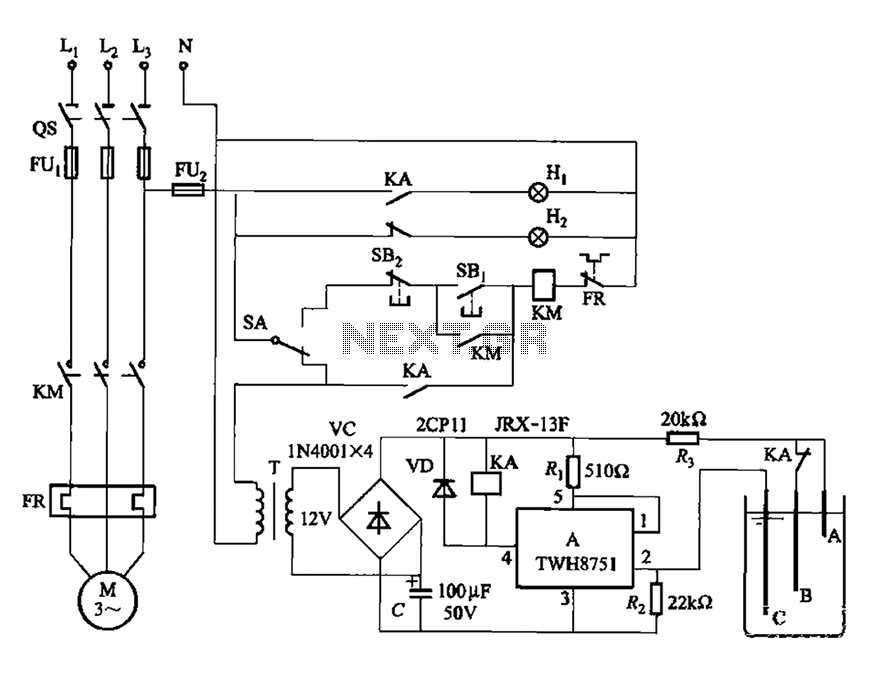
The power switch integrated circuit A features a straightforward design with high sensitivity, ensuring reliable operation. It is part of an automatic liquid level control circuit. When the water level at electrode B drops below 2 feet (0V), circuit...