
Easy exchange of magnetic saturation voltage regulator circuit

The magnetic saturation voltage regulator circuit is designed to stabilize output voltage levels by utilizing magnetic saturation principles. This circuit typically employs a magnetic core, which operates in saturation to regulate voltage, ensuring minimal fluctuations in output despite variations in load or input voltage. The primary components of this circuit include a transformer, diodes, and a feedback mechanism that monitors the output voltage.
The transformer is crucial in stepping down the input voltage to a manageable level before it is rectified by the diodes. The diodes convert the AC voltage from the transformer into DC voltage, which is then smoothed using capacitors to reduce ripple. The feedback mechanism is essential for maintaining voltage stability; it continuously compares the output voltage to a reference voltage and adjusts the control signal accordingly.
When the output voltage rises above the desired level, the feedback loop reduces the current flowing through the transformer, effectively bringing the output voltage back into the acceptable range. Conversely, if the output voltage drops, the feedback loop increases the current to compensate. This dynamic adjustment allows the magnetic saturation voltage regulator to maintain a constant output voltage even under varying load conditions.
The design of this circuit can be optimized for efficiency by selecting appropriate components and tuning the feedback loop for quick response times. Additionally, considerations for thermal management should be made, as components may generate heat during operation. Overall, the magnetic saturation voltage regulator circuit presents a reliable solution for applications requiring stable voltage regulation.Easy exchange of magnetic saturation voltage regulator circuit
Related Circuits
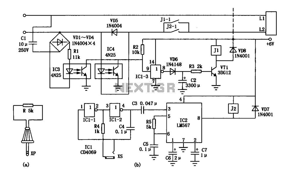
An electronic lock utilizing a telephone key, which is connected through a resistor plug, is integrated after the oscillator circuit's startup phase. The accuracy of the oscillation frequency determines whether the phone can be used for outgoing calls, while...

This circuit switch slowly on and off the internal lights in a car. The delaying time can be adjusted changing the values of the 10k, 4M7 resistors and capacitor. More: The BUZ74 can handle voltages of 500V, but you...
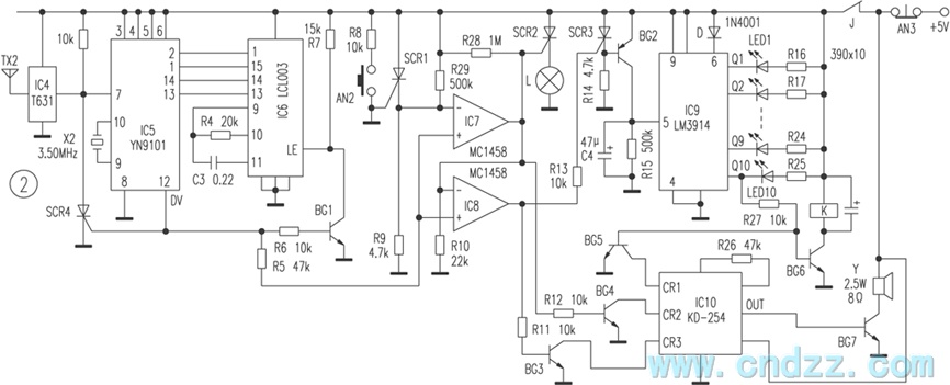
The wireless calling device consists of a calling unit and a host. These two components communicate using a DTMF encoder pulse. Each calling unit is assigned a unique code, although the circuits are identical. The calling unit is depicted...
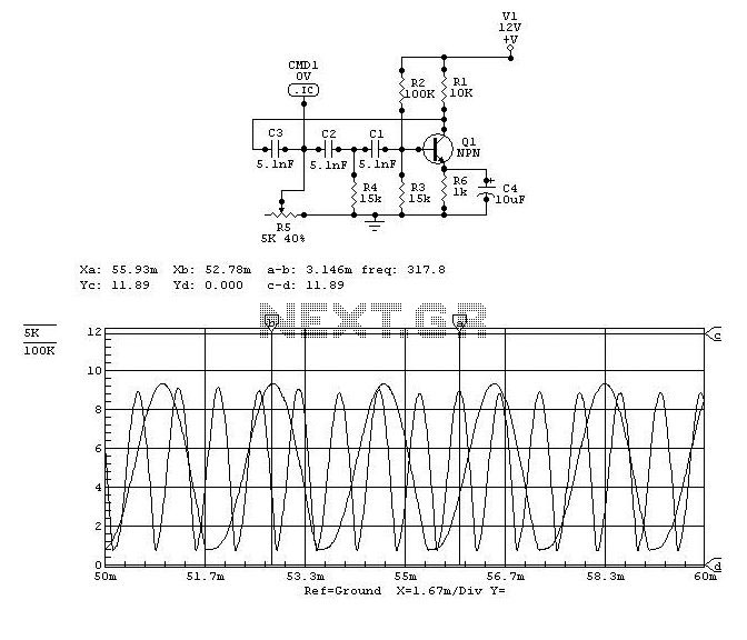
This project was a surprise as the BC547 transistor (equivalent to 2N2222) can be used to construct a 500mW linear amplifier that operates across the entire HF band with excellent spectral purity and without the need for neutralization. The...
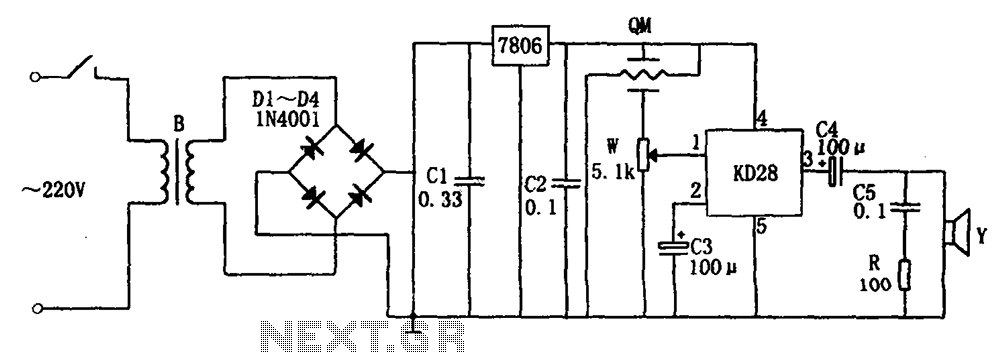
The system includes a gas-sensitive sensor element QM (type QM-N5), a buck rectifier, and regulator circuits, integrated circuits KD28, a speaker Y, and other components. The buck regulator circuit features a transformer rectifier and a bridge rectifier comprising diodes...
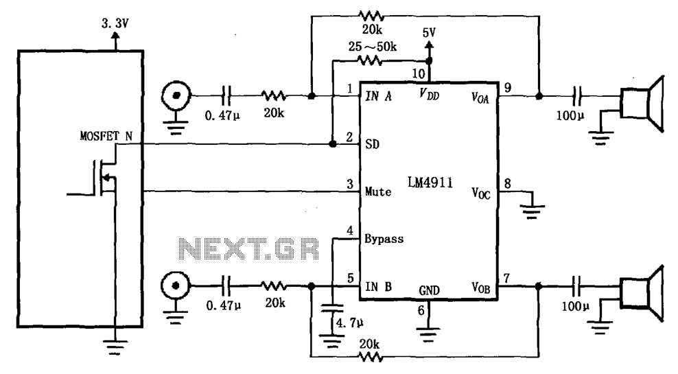
The circuit for the LM4911 demonstrates different power conduction times. It utilizes a controller, specifically the MOSFET LM4911 shutdown control (SD) terminal, to regulate the on-time of the amplifier. The LM4911 is a power amplifier designed for audio applications, providing...