
Telephone electronic lock circuit

The electronic lock circuit employs a telephone key mechanism that operates through a resistor plug. When the key is inserted, it completes a circuit that activates the oscillator, producing a specific frequency. This frequency is crucial for determining the system's response; if the frequency aligns with the predetermined value, the circuit allows for outgoing calls. This feature ensures that unauthorized users cannot make calls, as the system remains inactive without the correct key.
The unlocking mechanism is facilitated by a signal recognition circuit that identifies the specific frequency generated by the inserted key. Once the correct frequency is detected, the circuit activates the self-locking feature, which maintains the lock state until the key is removed. This self-locking capability adds an additional layer of security, ensuring that the phone remains inoperable without the proper key.
Overall, the electronic lock circuit is designed to provide a secure method for controlling telephone access, ensuring that only authorized users can make outgoing calls while allowing incoming calls to function normally. The integration of frequency recognition and self-locking mechanisms creates a robust system that enhances the security of telephone use.Electronic lock using the telephone key (resistor connected plug) is inserted after the oscillator circuit start-up circuit, and the oscillation frequency is accurate or not to decide whether to open the phone for outgoing calls, and answering external calls are not affected, which may ensure that only the person holding the lock key to use the telephone. Telephone electronic lock circuit is shown, it is mainly by the frequency key to unlock circuit, unlocking ring portion of the signal recognition circuit and self-locking circuit.
Related Circuits

This circuit utilizes LM358 operational amplifiers (or any single supply operational amplifier) to generate a pulse-width modulated (PWM) signal. The design was specifically created for a local marine repair company that requested a circuit that is easily repairable and...

Battery vampires are circuits designed to extract as much energy as possible from batteries or cells. They are not regulated drivers; rather, they are boost circuits that create a higher output voltage from a low input voltage and provide...
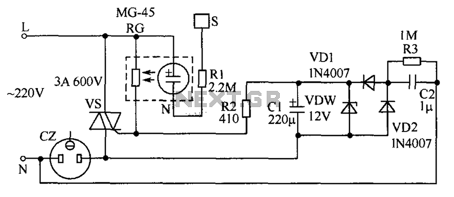
The circuit operates by detecting a finger touch on a metal sheet (S), which activates a neon tube light (N). The combination of the neon tube and a photoresistor (RG) acts as an optocoupler, reducing the resistance of RG....

The astable multivibrator circuit lacks a stable state. In the absence of an external signal, the internal transistors alternately switch between cutoff and saturation at a frequency determined by the RC time constants of the coupling circuits. Therefore, an...
This audio noise filter circuit is a bandpass filter designed for the audio frequency range. It effectively filters out unwanted signals that fall outside the audio frequencies. The circuit consists of two filters: a low-pass filter and a high-pass...

A low-cost, simple radio circuit schematic using an operational amplifier. This radio circuit diagram consists of a sensitive audio amplifier that receives strong signals. The presented radio circuit schematic utilizes an operational amplifier (op-amp) to create a cost-effective and straightforward...