
ECG telemetry circuit diagram

The described circuit serves as an educational tool for demonstrating the principles of electrocardiography and audio signal processing. The core component, the LM4250 operational amplifier, is utilized to amplify the weak ECG signal captured from the patient. The amplified signal is then fed into the NE566 voltage-controlled oscillator, which converts the varying voltage levels of the ECG signal into corresponding frequency changes. This modulation allows for the direct auditory representation of the electrical activity of the heart.
The output from the NE566 is connected to a small speaker, which translates the modulated signal into sound waves. This enables observers to hear the heartbeats and variations in heart rhythm in real-time, facilitating a better understanding of cardiac function. For telemetry applications, the circuit can be enhanced by incorporating a microphone that captures the sound output, allowing for remote monitoring of the ECG signal.
To connect the circuit to a patient, standard viscous monitor electrodes are recommended for optimal contact and signal quality. Alternatively, small metal pieces can be affixed to the patient’s wrist using a rubber band, ensuring that the electrical signals are reliably transmitted to the circuit. This setup allows for a practical demonstration of how electrical signals from the heart can be monitored and analyzed, making it an invaluable tool for educational purposes in electronics and biomedical engineering. The pitch of the sound produced varies with each heartbeat, providing an auditory cue that corresponds to the heart's electrical activity, thus illustrating the relationship between physiological signals and electronic processing.The circuit designed for teaching demonstration or experiment with it to hear the signal voltage electrocardiogram. ECG signal voltage is amplified by the LM4250 operational amplifier connected to a voltage-controlled oscillator NE566 to modulate the oscillator output is used to drive a small speaker, so you can hear the ECG signal. If you want to telemetry, you can use the microphone to pick up the sound output. To put this circuit and the patient connected, you can use the standard viscosity monitor electrodes can also be used a rubber band to tie small metal pieces on the patient's wrist.
Each pulse will cause the pitch frequency changes.
Related Circuits
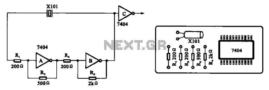
A clock oscillator is commonly utilized in digital signal processing circuits and microprocessor circuits. Digital signal transmission and signal processors necessitate a clock, which serves as the system's timing signal, while the data signal functions as a synchronization signal....
DC Motor Control Using a Single Switch. This simple circuit allows for the operation of a DC motor in both clockwise and counterclockwise directions, as well as stopping it using a single switch. The circuit utilizes non-latching push button...
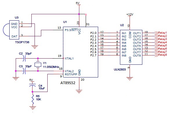
The infrared (IR) circuit is designed to control multiple devices using a TV remote. Unlike standard circuits that can typically switch only one device, this circuit allows for the operation of different devices with the same remote by utilizing...
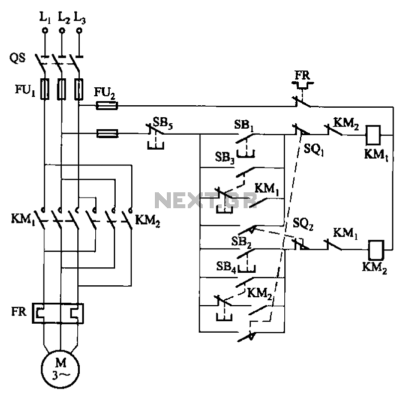
The circuit depicted in Figure 3-27 features a jog function that allows for precise adjustments of moving components. In the figure, SB3 and SB4 represent the forward jog and reverse jog buttons, respectively. When the SB3 button is pressed,...
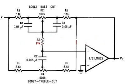
A simple tone control circuit can be designed using the LM833 operational amplifier along with a few external components. The LM833 is a dual general-purpose operational amplifier, specifically optimized for performance in audio applications. This tone control circuit utilizes...
The following circuit illustrates the TL084 integrated circuit (IC) used as a dynamo current voltage regulator, accompanied by a fuse box diagram. Features include a comprehensive control circuit that will... The TL084 is a quad operational amplifier that is commonly...