
Echo Bender V2

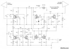
The proposed circuit schematic centers around the design of a delay effect pedal, which incorporates adjustable slide resistors for enhanced playability. This modification allows musicians to manipulate effects in real-time, providing a dynamic sound experience. The EchoBender schematic serves as the foundation, enabling the integration of features from the Rebote 2.5 Delay pedal, renowned for its rich delay tones.
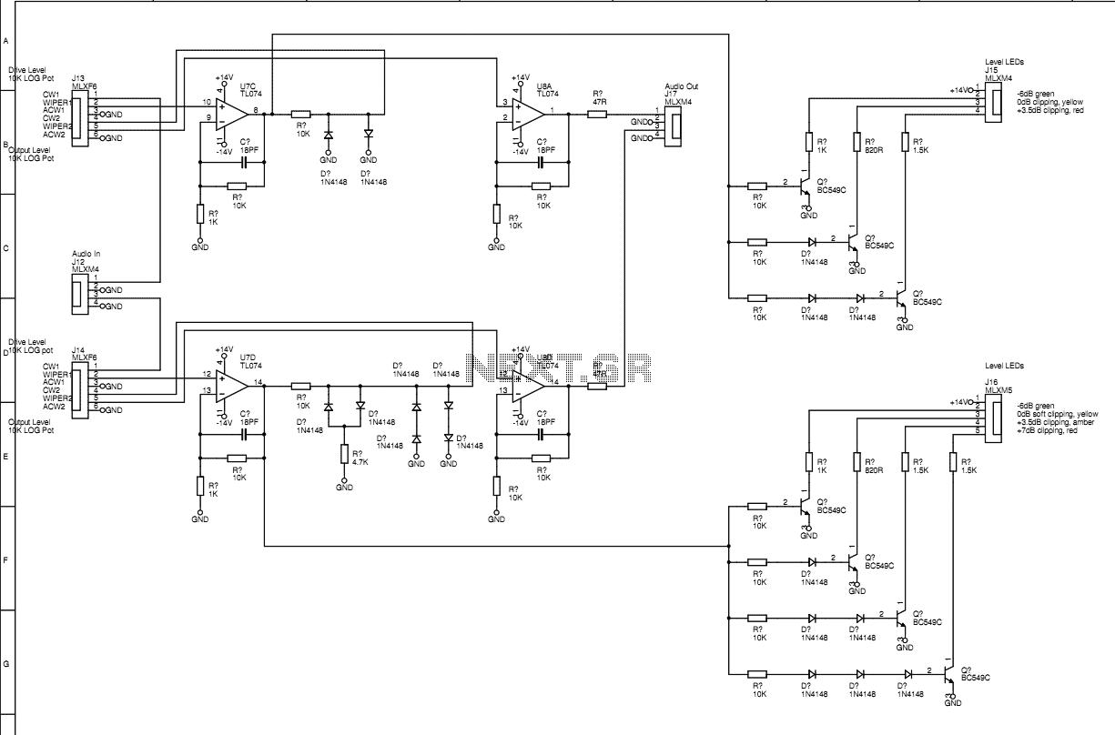
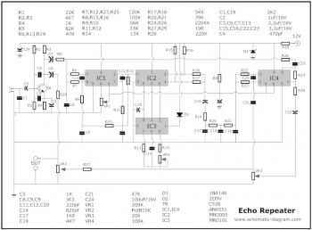
The circuit operates with a 9V DC power supply, which is critical for the functionality of the operational amplifier (TL072). The use of two 10k resistors in conjunction with a capacitor effectively halves the voltage, providing a stable 5V supply necessary for the delay IC. This dual-voltage setup not only ensures proper operation but also enhances the performance of the pedal.
In terms of component selection, a comprehensive parts list is essential for successful assembly. This list should include all resistors, capacitors, integrated circuits, and any additional components, such as the slide resistors and voltage regulator. Special attention should be given to the integration of a 20k resistor slider to facilitate volume control, as this will enhance the pedal's functionality and user experience.
The PCB layout, which is being developed using DIY Layout Creator, should ensure that each component is correctly placed to minimize noise and interference. Proper grounding and power supply routing for the TL072 operational amplifiers must be confirmed to prevent any operational issues. It is advisable to verify the schematic and layout thoroughly before proceeding with PCB fabrication, as this can mitigate potential troubleshooting challenges during the assembly phase.
Overall, this project presents an exciting opportunity to create a unique delay pedal that combines traditional design elements with modern performance capabilities, catering to musicians seeking innovative ways to manipulate sound.It seems a lot of the soundscape effect comes from turning the pots as you play. Could you make a version with slide resistors instead of pots and put them on foot pedals so you can manipulate them as you play yeah, schematic! very cool of you to offer, would love to build one. funny youre based in troy now, i left there for nyc around the ti me you left nyc for troy. say hi to scully for me! [. ] schematic is largely (read: almost entirely) based upon Casper Electronics`EchoBender pedal, which is in turn largely based on Tonepad`sRebote 2. 5 Delay pedal, which is in turn, more [. ] [. ] schematic is largely (read: almost entirely) based upon Casper Electronics`EchoBender pedal, which is in turn largely based on Tonepad`sRebote 2.
5 Delay pedal, which is in turn, more [. ] has anyone attempted this I am kind of absent minded and if anyone has put together a complete parts list I would love to see it. I am just afraid to start ordering the parts and realize that I don`t have them all when I start assembly.
I realize that I could get it all off the scematic but i already messed up once copying them and I am afraid to start. the voltage in to the circuit is 9v dc this is then halfed between two 10k resistors and a cap so you can use a dual supply op amp (Tl072) the 5v is for the the delay ic this is obtained with the use of a 5v voltage reg @mrmrshoes: could you please sent me the second pcb layout to lucas.
alvarez96@hotmail. com. I urgently need it and I`m not to experienced with PCB Software. Please, I would very much appreciate it. I was wondering if anyone knows where I can add/replace a 20k resistor slider to control the volume input. I am building this delay pedal in this casing and would love to use the original slider. Hi, I am currently transfering this to a layout (in DIY Layout Creator) I have a question concerning the left-most TL072, doesn`t it need 9v power and grounding as the right one I`ve not got round to building the PCB hardware version so etch this at your own risk.
It looks good (just checked the schematic and layout) but you can never tell until you build and trouble shoot. 🔗 External reference
Related Circuits
In the past, depth measurement of the sea bottom was performed using a "bullet," which was a heavy lead object lowered into the water from a calibrated rope. When the bullet reached the seabed, the depth could be read...
This is probably one of the most legendary fuzz pedals that has ever existed, and for good reason too! This thing can produce some completely saturated fuzz that is capable of slipping into feedback easily if you crank it...
The PT2399 digital echo circuit schematic is an electronic design that utilizes the PT2399 integrated circuit (IC) for audio applications. This digital echo processor, based on CMOS technology, incorporates both analog-to-digital conversion (ADC) and digital-to-analog conversion (DAC) processes for...
This is a 3U rack unit with standard mains power supply. It provides audio routing and speed control for two domestic three-head cassette tape machines such that they can be used to create authentic 1960s style tape flanging effects....
This simple circuit amplitude-modulates a single tone to approximate the echo effect similar to that produced by sonar apparatus. Individuals familiar with sonar-equipped vessels may recognize the imaginative similarities between this basic scheme and actual sonar technology. This circuit...
The circuit described is a combination of an echo chamber circuit, which creates a repeated sound effect similar to an echo in a cave, and a robot voice effect circuit that modifies an audio signal to produce a robotic...