
Flanger and Echo circuit
The circuit design for this 3U rack unit is centered around providing a versatile platform for audio manipulation using cassette tape machines. The unit is powered by a standard mains power supply, ensuring compatibility with most audio setups. The primary function of the unit is to facilitate audio routing and speed control for two three-head cassette tape machines, which can be employed to generate 1960s-style tape flanging effects.
The audio inputs and outputs are connected via dual phono leads, allowing for seamless integration with existing audio equipment. The speed control mechanism utilizes a three-wire connection to manage the capstan motor of one of the tape machines. This control can be adjusted either manually via a front panel knob or externally through voltage control, providing flexibility in achieving the desired flanging effect.
The internal circuitry includes standard voltage regulators to provide stable +/-5V reference rails, essential for the operation of the speed control and audio processing functions. The design incorporates an LM317 voltage regulator that is adjusted to maintain the appropriate voltage for the motor, ensuring that it operates efficiently despite the inherent limitations of the motor's internal speed control.
The audio processing section features multiple operational amplifiers configured to sum and buffer audio signals from the tape machines. These op-amps allow for the combination of source and feedback signals, enabling complex audio effects like tape echo and feedback loops. The variable gain stage, formed by the op-amps and 22K linear pots, allows for fine-tuning of the output signal's gain, providing a range of +/-1.0 for dynamic control over the audio output.
Additionally, the unit includes clipping circuits designed to prevent tape overload by pre-clipping feedback signals. These circuits are equipped with LED indicators to provide visual feedback on signal levels, assisting users in managing audio levels effectively during operation. The inclusion of soft clipping features enhances the audio quality, allowing for a smoother transition into clipping without harsh distortion.
Overall, this 3U rack unit is a sophisticated tool for audio engineers and musicians seeking to recreate vintage tape effects while offering modern control and flexibility in audio processing.This is a 3U rack unit with standard mains power supply. It provides audio routing and speed control for two domestic three-head cassette tape machines such that they can be used to create authentic 1960s style tape flanging effects. The tape machines link to the rear of the unit with a total of four dual phono leads. The speed control of one machine is achieved by voltage control of the capstan motor connected by a three wire connection.
The flange effect can be adjusted manually on a front panel control or externally by voltage control. There are sufficient jack patch sockets and input-output flexibility such that the tape machines can also be used for tape echo or tape feedback effects.
Inverting gain controls enable different tape decks to be used which may have an overall inverting signal path between the record inputs and the downstream tape monitor outputs. This sheet has standard regulators to provide regulated +/-5V reference rails and the motor speed control circuitry. Tape machine A in this prototype setup has a 12Vd.c. motor which has an internal electronic speed control, adjustable on a screwdriver control through a small hole in the rear.
The motor has been set to its maximum speed on this control. The circuit here is provided with the 12V supply which would normally drive the motor with its internal regulation. This is reduced to a nominal *V which gives approximately the correct normal running speed. The speed regulator internal to the motor is thus running in drop-out, and speed regulation will not be particularly good.
However this is not a major problem for a flanging effect where the speed is usually changing constantly. It should be considerably more controllable than the historic method of applying finger pressure to rotating tape spools.
The external regulator is a traditional LM317, set to provide *V if the lower 1K resistor were to be grounded. The op-amp arrangement lifts this node to a higher voltage which is seen directly impressed on the voltage output.
The op-amp input side sums with appropriate scaling the manual control voltage from the front panel pot with the external control voltage. An adjustment preset voltage is also summed in and sets the normal mid-point running speed. This sheet shows the main audio sections. The first four op-amps sum each dual audio input brought in on J5 and J11. This allows a source input and a feedback input to be summed easily. The summing amps provide buffering for the tape record inputs which are connected via J6 to phono sockets on the rear panel.
The returns from the tape outputs enter on J7. They are sent to the CW ends of 22K linear pots on the front panels. In conjunction with amps U6A-D this forms a variable gain stage which can change the gain of the tape output signal by ±1.0. The tape outputs are sent to two split jack sockets each via J10. The splits allow the signal to be used as output and to be fed back to one of the input sums for echo.
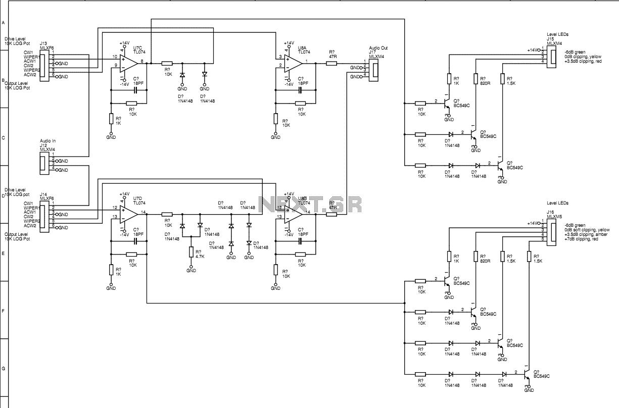
Two summing amplifiers sum the outputs from each of the variable and fixed speed tape decks to create two independent flange outputs. These are presented on two front panel jacks via J9. This sheet has the two clipping circuits which can be used to pre-clip feedback signals to limit actual tape overload.
These can also be used externally for other effects. On clipper 1, a three LED level indicator shows green, yellow and red. Yellow is the clipping start point. Green is -6dB from clipping and red indicates +3.5dB from the clipping start point. A completely standard double-diode circuit is used. On clipper 2 a second knee is added to the circuit and there is a four LED indicator. Green indicates a signal -6dB from the first clipping point. When the first knee is reached the first yellow LED will light and there is a region of 3.5dB where the gain is reduced by 6dB. This is a region of soft clipping. When the second yellow LED lights the signal is +3.5dB from the soft clipping start and standard clipping begins.
The red LED lights at +6dB from the start of soft clipping and is +2.5dB above the hard clipping point. 🔗 External reference
Related Circuits
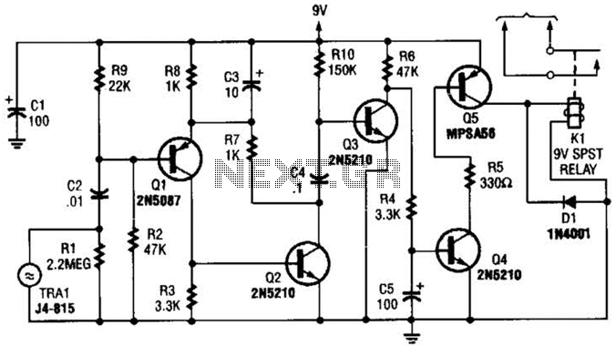
A GC Electronics P/N J4-815 transducer is utilized to receive 40-kHz acoustic remote-control signals. The receiver activates a relay to control another circuit. The GC Electronics P/N J4-815 transducer is designed specifically for the reception of 40-kHz acoustic signals, which...
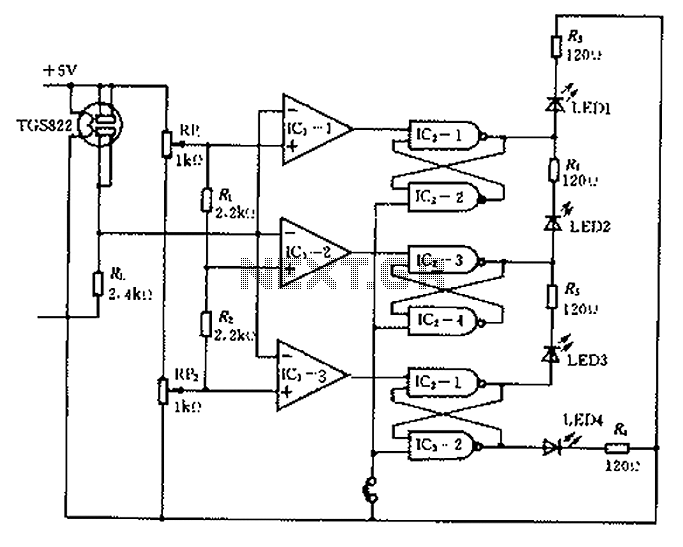
Ceramic gas sensors can be utilized to analyze the content of alcohol vapor. With the appropriate sensor circuit, it is possible to detect blood alcohol content. The operating principle is straightforward: if blood alcohol content is present in a...
The circuit was designed to obtain signals through amplitude modulation, exhibiting good sensitivity and selectivity. Amplitude modulation. The amplitude modulation (AM) circuit is engineered to effectively capture and process radio frequency signals. The design focuses on achieving high sensitivity, allowing...
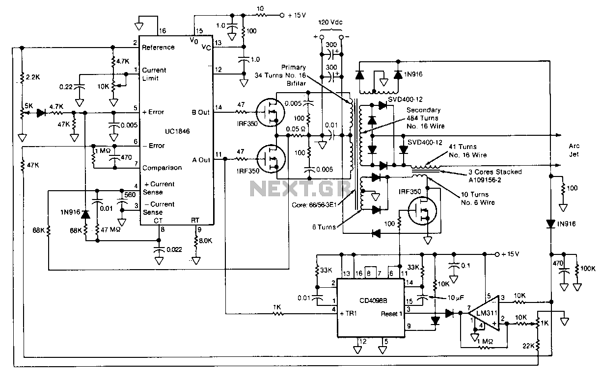
This circuit for starting arc jets and controlling them in steady operation is capable of high power efficiency and can be constructed in a lightweight form. The design comprises a pulse-width-modulated power converter, which is configured in a closed...
This inductance meter serves as an adapter for a digital voltmeter (DVM), enabling the voltmeter to measure the value of inductors. The inductance meter is particularly useful in designing switch mode power supplies, as it often requires hand-winding coils...
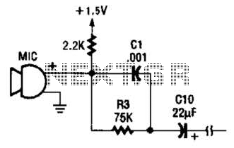
This circuit is suitable for using an electret microphone for various applications. A 1.5-V battery is utilized. CI and R3 provide treble boost and bass cut; they can be eliminated if desired. The described circuit employs an electret microphone, which...
Warning: include(partials/cookie-banner.php): Failed to open stream: Permission denied in /var/www/html/nextgr/view-circuit.php on line 713
Warning: include(): Failed opening 'partials/cookie-banner.php' for inclusion (include_path='.:/usr/share/php') in /var/www/html/nextgr/view-circuit.php on line 713