
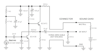
ECM Mic Preamplifier

The circuit in question is designed to amplify signals from an electret condenser microphone, which is known for its sensitivity and compact size. The selection of low-noise transistors, such as the BC549C or BC109C, is crucial for maintaining a high signal-to-noise ratio, particularly in audio applications where clarity and fidelity are paramount. The self-biasing feature of the circuit allows it to automatically adjust the quiescent point, optimizing performance without the need for manual calibration.
The electret microphone operates effectively within the specified voltage range, ensuring compatibility with various power sources. The use of a 1k resistor to limit current is a standard practice that protects the microphone element from excessive current, while the recommendation to increase this resistor to 2.2k for higher supply voltages ensures that the microphone operates safely within its specifications.
The low output impedance of the circuit enhances its ability to drive long cable runs without significant signal degradation, which is particularly beneficial in professional audio settings. The absence of the need for screened cables simplifies installation and reduces costs, making this circuit suitable for various applications, including live sound reinforcement and recording.
The amplifier's dynamic range is impressive, allowing it to capture both soft and loud sounds effectively. However, it is essential to consider the input characteristics of any connected equipment. Ensuring that the amplifier or tape deck does not overload is critical to maintaining audio integrity and preventing distortion. This design approach ensures versatility and reliability in a wide range of audio environments.Both transistors should be low noise types. In the original circuit, I used BC650C which is an ultra low noise device. These transistors are now hard to find but BC549C or BC109C are a good replacement. The circuit is self biasing and will set its quiescent point at roughly half the supply voltage at the emitter of the last transistor. The electre t condenser microphone (ECM) contains a very sensitive microphone element and an internal FET preamp, a power supply in the range 2 to 10 volts DC is therefore necessary. Suitable ECM`s may be obtained from Maplin Electronics. The 1k resistor limits the current to the mic. This resistor should be increased to 2k2 if a supply voltage above 12 Volts DC is used and is not needed if the Mic insert is dynamic.
The output impedance is very low and well suited to driving cables over distances up to 50 meters. Screened cable therefore is not necessary. The noise response of the amplifier measured across the 10k load is shown below. Please note that this plot was made with the mic insert replaced by a signal generator. This preamplifier has excellent dynamic range and can cope with anything from a whisper to a loud shout, however care should be taken to make sure that the auxiliary equipment i. e. amplifier or tape deck does not overload. 🔗 External reference
Related Circuits
The sound card for a PC typically includes a microphone input, speaker output, and occasionally line inputs and outputs. The microphone input is specifically designed for dynamic microphones with an impedance range of 200 to 600 ohms. An adaptation...
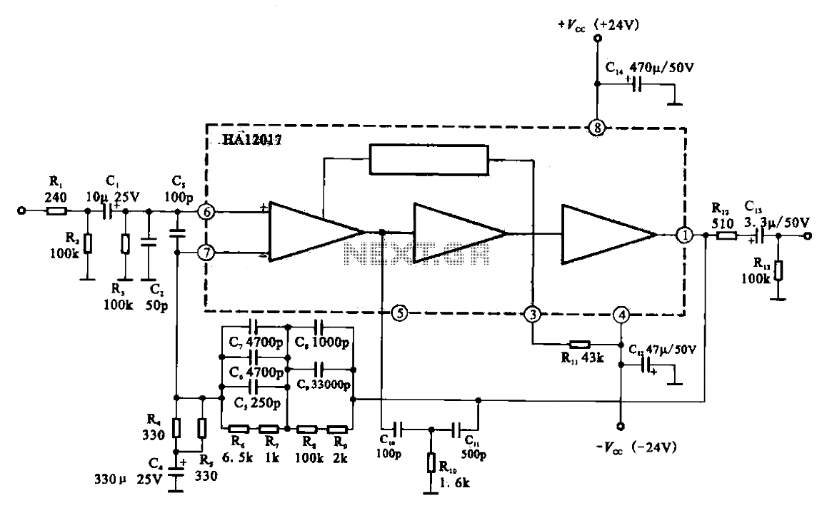
Low-noise preamplifier circuit. This circuit demonstrates a typical low-noise preamplifier design, which can be utilized to amplify signals from sources such as magnetic heads and microphones within audio applications. The input signal is coupled through a capacitor and subsequently...
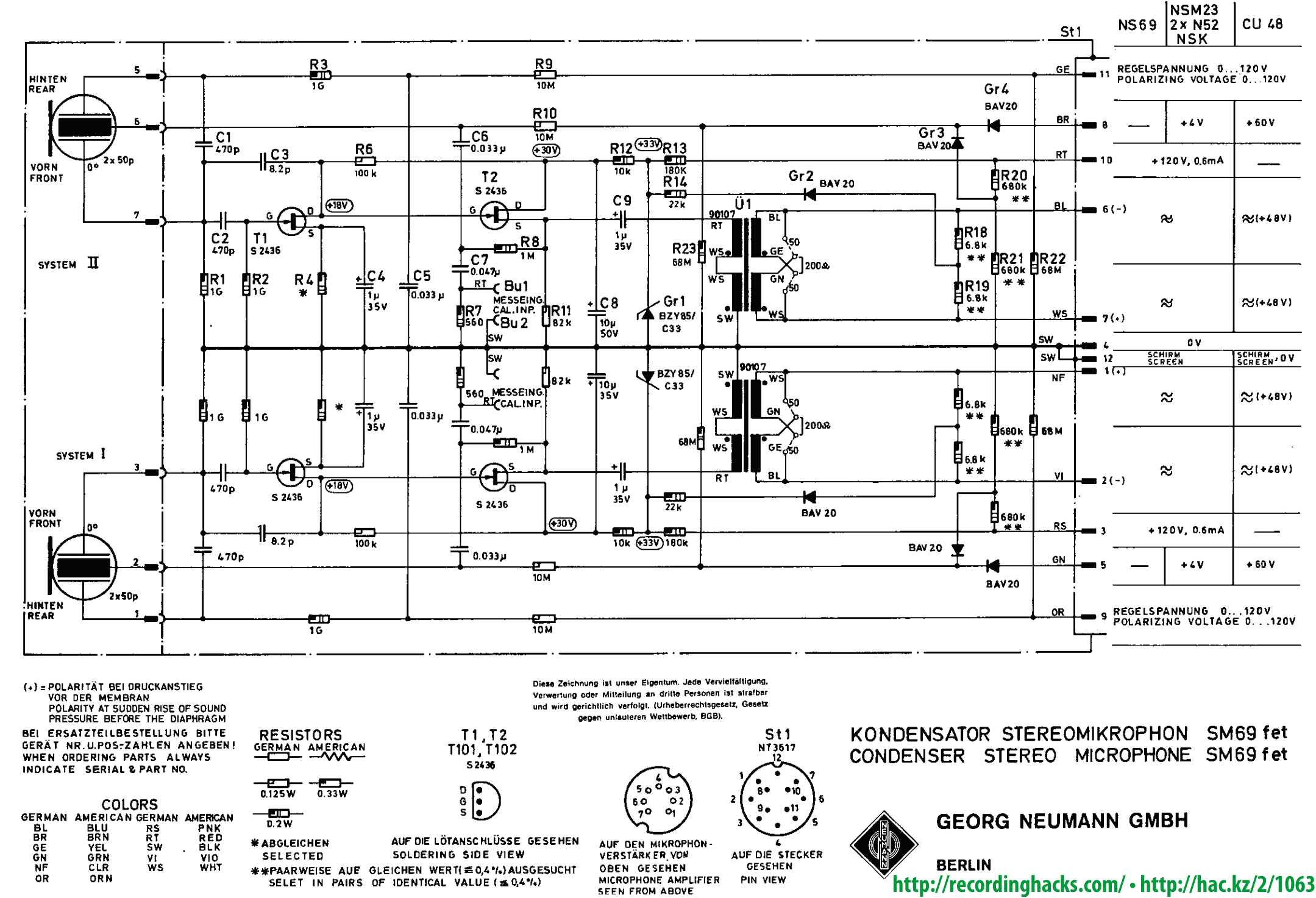
Both utilized a pair of capsules from Neumann's K67 family, stacked vertically, with the upper capsule capable of rotating 270° relative to the lower one (presumably between -90° and +180°, similar to the USM 69). The capsule employed is...
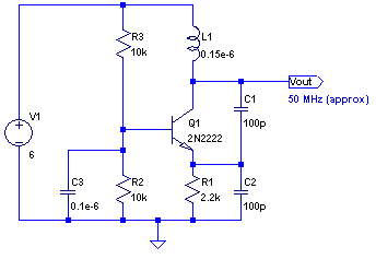
The core of any transmitter is typically an oscillator circuit, and in simple transmitters, such as QRSS devices, a crystal is often used. Frequency adjustment is achieved by modifying the capacitance to ground on one of the crystal's legs....
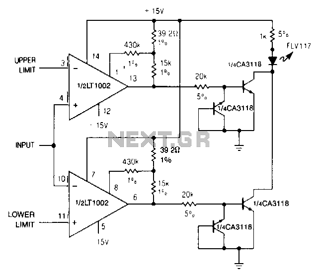
When the upper or lower limit is exceeded, the LED lights up. Positive feedback to one of the nulling terminals creates 5 to 20 pV of hysteresis on both amplifiers. This feedback changes the offset voltage of the LT1002...

Cybernetic Micro Systems' CY545 User Manual (Chapter 13) - CY545 Thumbwheel Switch Support. External thumbwheels enable manual entry of parameters for control functions, facilitating stand-alone control. The CY545 Thumbwheel Switch is designed to provide a user-friendly interface for manual parameter...