
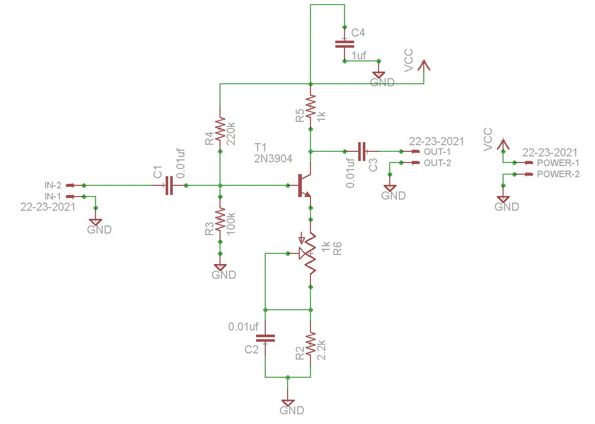
ECM microphone preamplifier

The circuit design incorporates two low-noise transistors, enhancing the overall performance and signal integrity of the audio system. The BC650C transistor, known for its ultra-low noise characteristics, was initially selected for its superior performance in audio applications. The BC109C, as a replacement, retains adequate low-noise performance while being more readily available. The configuration allows for flexibility in device selection without compromising the circuit's functionality.
The quiescent point, set at half the supply voltage, ensures that the final transistor operates efficiently, providing optimal amplification of the audio signal. This design consideration is critical for achieving a balanced output and minimizing distortion during signal processing.
The electret condenser microphone (ECM) plays a pivotal role in capturing sound. Its internal FET preamplifier amplifies the weak signals generated by the microphone element, making it suitable for low-voltage operation. A power supply of 2 to 10 volts DC is required to ensure proper functionality, which can be easily sourced from various power supplies available on the market.
The inclusion of a 1k ohm resistor serves to limit the current flowing to the microphone, protecting it from excessive current that could lead to damage. This resistor is a crucial component in maintaining the integrity of the microphone's operation.
The circuit's output characteristics are designed to accommodate long cable runs, with an output impedance that remains low. This feature allows for the use of standard cables over distances up to 50 meters without significant signal degradation, thus negating the necessity for screened cables. Overall, this circuit design exemplifies an efficient and effective approach to audio signal amplification, ensuring high-quality performance in various applications. Both transistors are low noise types. In the original circuit, I used BC650C which is an ultra low noise device. These transistors are now hard to find but BC109C are a good re placement. The circuit is very device tolerant and will set its quiescent point at roughly half the supply voltage at the emitter of the last transistor.The electret condenser microphone (ECM) contains a very sensitive microphone element and an internal FET preamp, a power supply in the range 2 to 10 volts DC is therefore necessary. Suitable ECMs may be obtained from Maplin Electronics. The 1k resistor limits the current to the mic. The output impedance is very low and well suited to driving cables over distances up to 50 meters. Screened cable therefore is not necessary.
Related Circuits
Adapting a failed Tesla coil into a crystal radio set for demonstration purposes has presented challenges, particularly with antenna size for optimal signal reception. It has been noted that an ideal AM antenna should range between 100 to 500...
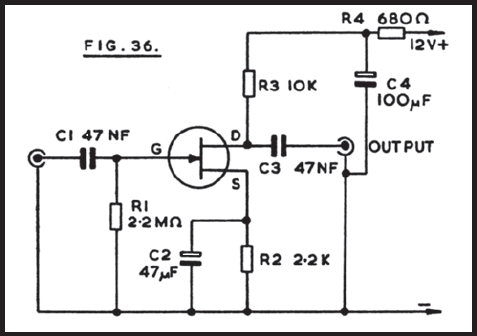
Figure 36 illustrates the circuit of a preamplifier featuring a high impedance input and an output circuit designed for coupling to a main amplifier. This configuration is particularly advantageous for applications such as amplifying the signal from a crystal...
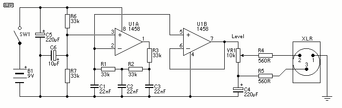
This unit would be mounted in a small plastic or preferably metal box, with a 9V battery, level control, a male XLR connector (same as on a mic) and a switch. Current drain is low, since the circuit only...
More: A comprehensive electronic schematic is required to illustrate the functionality and interconnections of various components within a circuit. The schematic should clearly depict the arrangement of components such as resistors, capacitors, diodes, transistors, and integrated circuits, along with...
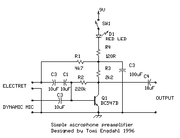
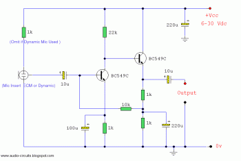
This is a simple microphone preamplifier circuit designed for use between a microphone and a stereo amplifier. This circuit is compatible with standard home stereo amplifier line, CD, aux, and tape inputs. It can accept both dynamic and electret...
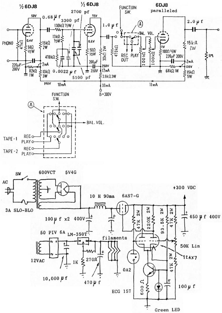
6DJ8 Tube RIAA Phono and Line Preamplifier Schematic. The high-tension (HT) power supply employs tube rectification and regulation. The 6DJ8 tube RIAA phono and line preamplifier schematic is designed to amplify audio signals from phono cartridges and line-level sources, utilizing...