
Crystal Microphone Preamplifier

This preamplifier circuit is designed to enhance weak audio signals, making it ideal for use with high-impedance microphones, such as crystal types. The high input impedance ensures minimal loading on the microphone, preserving the integrity of the audio signal. The output stage is configured to interface seamlessly with a main amplifier, facilitating effective signal transmission.
The input stage comprises a capacitor (C1) that blocks any DC offset from the microphone while allowing the AC audio signal to pass through. This is critical for ensuring that only the desired audio frequency components are amplified. The use of a shielded lead for the output connection minimizes interference and noise pickup, which is particularly important in audio applications.
Resistor R4 and capacitor C4 work together to stabilize the power supply to the circuit. R4 acts as a load resistor, determining the gain of the amplifier and influencing the overall output impedance. The value of R4 can be modified based on the supply voltage used, allowing for flexibility in circuit design. Capacitor C4 serves to decouple the power supply, filtering out any high-frequency noise that could affect circuit performance.
The choice of the 2N3819 FET provides a low-noise amplification solution, suitable for audio applications. Its characteristics allow for efficient signal amplification while maintaining a high input impedance. The potential for integrating this preamplifier onto a small insulated board simplifies the overall design and assembly process, enabling compact and efficient circuit layouts.
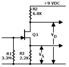
In summary, this preamplifier circuit is an effective solution for boosting low-level audio signals, with careful consideration given to component selection and circuit layout to ensure optimal performance and reliability. Proper placement away from high-current circuits is crucial to avoid interference, ensuring that the amplified signal remains clean and free from unwanted artifacts.Figure 36 is the circuit of a preamplifier with high impedance input and an output circuit allowing coupling to a main amplifier. It will be found extremely useful for purposes such as boosting the signal from a crystal microphone.
The input socket, connected to C1, should take the microphone or other input plug, and a screened lead should be prep ared to connect output and main amplifier. R4 and C4 provide smoothing and decoupling, so that current can generally be drawn from the main amplifier. It is preferable to use a 2-way power supply cord, not relying on the outer conductor of the audio lead for the negative circuit.
A 12v supply is not essential, and the value of R4 may if necessary be altered in value to suit other voltages. The 2N3819 and other audio and general purpose FETs are suitable. In some circumstances it may be possible to build this stage on a small insulated board which can be included in the main amplifier.
This will greatly ease overall assembly. Alternative sockets can allow the preamplifier to be omitted, or included for greater sensitivity, as necessary. It should be clear of AC, power, speaker or similar circuits carrying high current or audio signals, to avoid any difficulties from unwanted feed-back.
🔗 External reference
Related Circuits
This circuit was submitted by Graham Maynard from Newtownabbey, Northern Ireland. It has an exceptionally fast high-frequency response, as demonstrated by applying a 100kHz square wave to the input. All graphs were produced using Tina Pro. The circuit in question...
The J201 JFET operates optimally at 10 volts, with a minimum current requirement of 0.5 mA. These specifications are considered ideal, but the actual performance can vary significantly, typically within a range of three to five times. Recent tests...
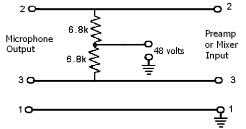
These devices require power to operate. This power can be supplied by a battery inserted into the microphone, a separate dedicated power supply with a specialized multi-pin cable, or most commonly, phantom power. Phantom power is supplied by a...
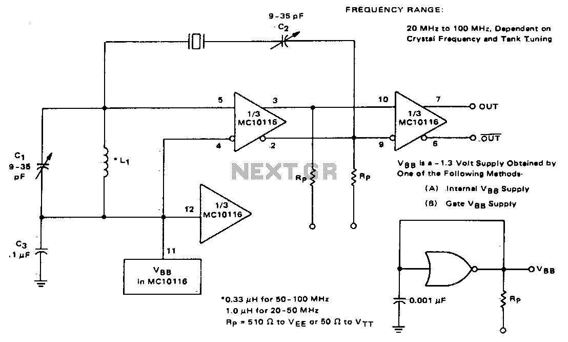
This circuit utilizes an adjustable resonant tank circuit that ensures operation at the desired crystal overtone. Capacitor C1 and inductor L1 form the resonant tank circuit, which can be adjusted to achieve a resonant frequency ranging from approximately 50...
The circuit diagram of a guitar preamplifier is designed to accept any standard guitar pickup. This preamplifier is versatile, featuring two signal outputs. A typical configuration involves a pickup attached to the guitar headstock, where the pickup device consists...
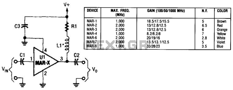
In this basic MAR-x-based circuit, both the input and output consist of a single DC-blocking capacitor (C1 for the input and C2 for the output, respectively). The DC power supply network, which includes L1 and R1, is connected to...