
Economical Pump Controllers

The automatic pump controller employs a straightforward yet effective design that leverages the properties of CMOS technology for reliable operation. The CD4001 chip serves as the core logic component, handling the decision-making process based on the input from the water-level sensors. The sensors, typically two conductive probes, detect the water levels by measuring conductivity between them. When the water level in the tank drops below the low threshold (L), the circuit activates the pump, assuming the reservoir level is sufficient (above R). As the water fills the tank and reaches the upper threshold (M), the circuit disengages the pump, preventing overflow and conserving energy.
This controller is particularly beneficial in applications where continuous monitoring and control of water levels are required. The design's resilience against transient water level fluctuations ensures that the pump operates only when necessary, thereby prolonging the lifespan of both the pump and the controller. The use of non-mechanical sensors minimizes maintenance needs, making it ideal for remote or hard-to-access installations.
In scenarios where constant fluid level maintenance is desired, the proximity of the probes M and L can be adjusted to create a narrow band of operation. This setting allows for precise control over fluid levels, which is crucial in applications such as aquariums, chemical storage, or irrigation systems.
While the system is highly adaptable, its limitations regarding non-conductive fluids must be acknowledged. To accommodate such fluids, modifications to the sensor design may be necessary, potentially involving the integration of capacitive sensors or other technologies capable of detecting non-conductive levels without altering the existing circuit structure. Overall, the automatic pump controller represents a robust solution for efficient water management in various settings.The automatic pump controller eliminates the need for any manual switching of pumps installed for the purpose of pumping water from a reservoir to an overhead tank (refer Fig. 1). It automatically switches on the pump when the water level in the tank falls below a certain low level (L), provided the water level in the reservoir is above a certain
level (R). Subsequently, as the water level in the tank rises to an upper level (M), the pump switched off automatically. The pump is turned on again only when the water level again falls below level L in the tank, provided the level in the reservoir is above R.
This automated action continues. The circuit is designed to ‘overlook ’ the transient oscillations of the water level which would otherwise cause the logic to change its state rapidly and unnecessarily. The circuit uses a single CMOS chip (CD4001) for logic processing. No use of any moving electro-mechanical parts in the water-level sensor has been made. This ensures quick response, no wear and tear, and no mechanical failures. The circuit diagram is shown in Fig. 2. The device performed satisfactorily on a test run in conjunction with a 0. 5 HP motor and pump. The sensors used in the circuit can be any two conducting probes, preferably resistant to electrolytic corrosion.
For instance, in the simplest case, a properly sealed audio jack can be used to work as the sensor. The circuit can also be used as a constant fluid level maintainer. For this purpose the probes M and L are brought very close to each other to ensure that the fluid level is maintained within the M and L levels. The advantage of this system is that it can be used in tanks/reservoirs of any capacity whatsoever. However, the circuit cannot be used for purely non-conducting fluids. For non-conducting fluids, some modifications need to be made in the fluid-level sensors. The circuit can however be kept intact. 🔗 External reference
Related Circuits
The SP6691 circuit is designed to provide a high output voltage using a lower voltage boost regulator by incorporating a charge pump circuit. This configuration can convert a standard 30V boost regulator into a 60V boost regulator if necessary....
.jpg)
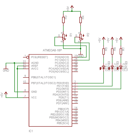
This is a general-purpose remote control project utilizing programmable PIC microcontrollers (PIC16F628, PIC16F630, PIC16F684). Schematics are provided for using infrared (IR) or radio frequency (RF) media. For those unfamiliar with microcontroller programming, fixed encoder and decoder integrated circuits can...
This is an image Schematic. No Description available. The provided input indicates that there is an image schematic without any accompanying description. In scenarios where a schematic is presented, it typically contains graphical representations of electronic components and their...
Neural networks are a broad topic. This example demonstrates how to create a basic neural sensor that takes resistive readings from multiple sensors, multiplies them by a weight factor, and then sums the results. The results are compared to...
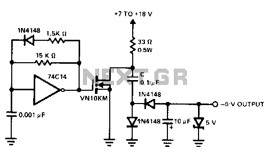
A charge pump is a straightforward method for generating a low-power voltage supply of opposite polarity from the main supply. The 74CL4 IC serves as a self-oscillating driver for the MOSFET power switch, producing a pulse width of 6.5...
This document serves as a continuation of the previous work on PWM controllers utilizing 555 timers. The new design incorporates microcontrollers and MOSFETs in place of the 555 integrated circuits and transistors. Two versions have been developed: one equipped...