
economy radar detector

The radar detector circuit employs a 1458 dual operational amplifier (op-amp) to effectively detect radar signals. The first op-amp is configured as a current-to-voltage converter, which translates the incoming radar signal current into a corresponding voltage. This conversion is critical for the subsequent processing of the signal. The output from this op-amp is then fed into the second op-amp, which is configured as a buffer. The buffering stage is essential as it ensures that the output can drive a piezo transducer without loading down the previous stage, thus maintaining signal integrity.
The component C1 plays a pivotal role as the radar signal detector, and its performance can be influenced by the physical characteristics of the leads connected to it. The length of these leads is crucial; for optimal performance with typical road radar systems, they should be approximately 0.5 to 0.6 inches long. This dimension helps to tune the circuit's response to the radar frequencies of interest while minimizing interference from background noise.
Resistor R5 is a critical component for setting the switching threshold of the second op-amp. Proper adjustment of R5 allows the circuit to distinguish between actual radar signals and background noise. Initially, the threshold is set so that the circuit just begins to trigger on background noise, and then it is slightly adjusted to prevent false triggering. This careful calibration ensures that the radar detector operates effectively in different environments and under varying conditions.
Overall, this radar detector circuit demonstrates a straightforward yet effective design utilizing a dual op-amp configuration, with key components selected to optimize performance for real-world applications.This circuit uses a 1458 dual op-amp to form a radar detector. C1 is the detector of the radar signal. The first op-amp forms a current-to-voltage converter and the second op-amp buffers the output to drive the piezo transducer. R5 sets the switching threshold of the second op-amp; normally it is adjusted so that the circuit barely triggers on bac
kground noise, then it`s backed off a bit. The response of the circuit may be tuned by adjusting the length of the leads on C1. For typical road-radar systems, the input capacitor`s leads should be about 0. 5 to 0. 6 inches 🔗 External reference
Related Circuits
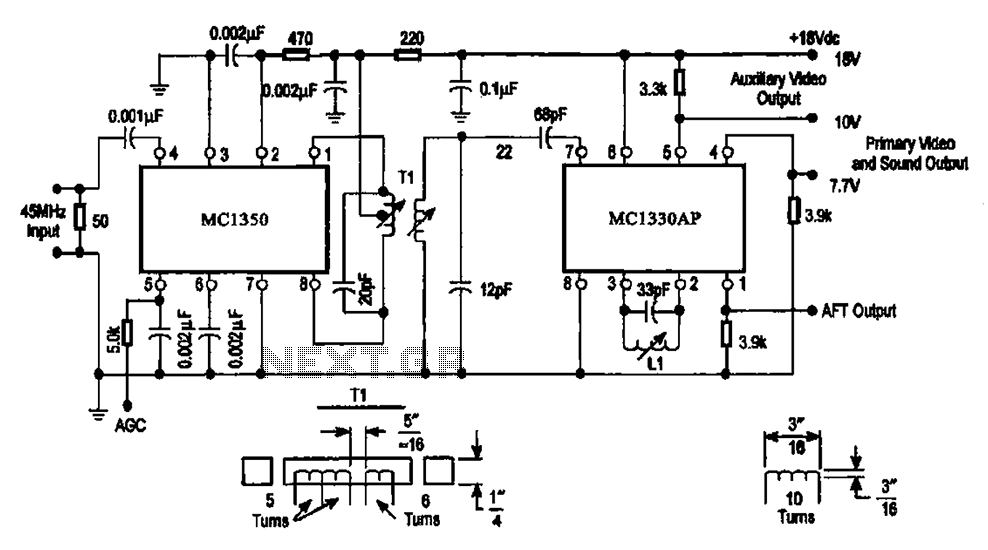
The circuit features an IF processing section utilizing the MC1350 and a video detector, the MC1330AP, which are integrated to form a combined video processing system. The modulation of the circuit is dependent on the image signal, with the...
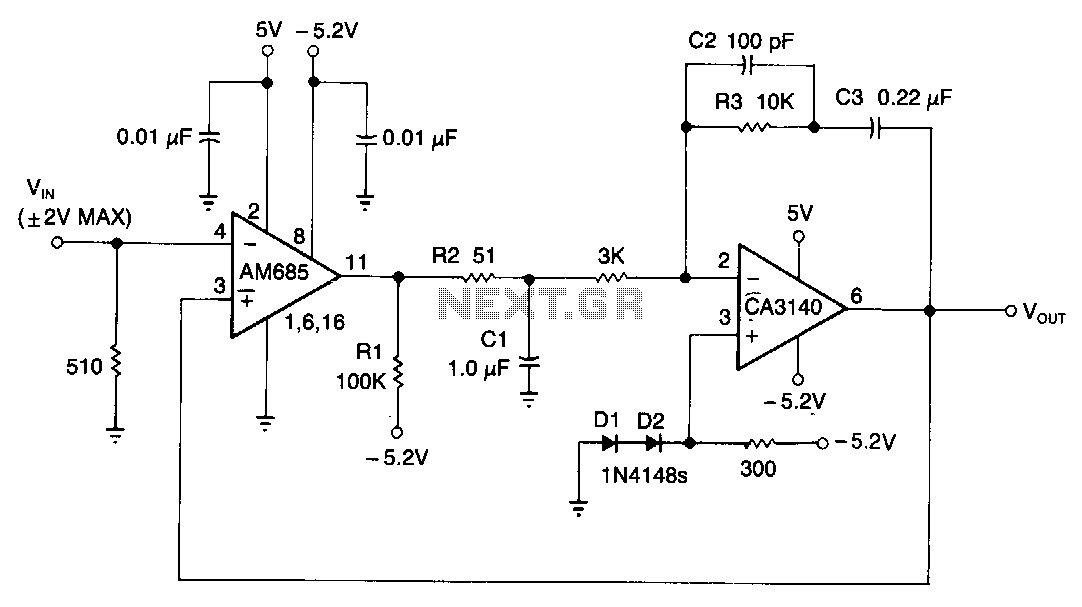
This circuit is capable of detecting positive peaks for signal frequencies exceeding 5 MHz, achieving an accuracy of ±1% for signal amplitudes ranging from 400 mV to 4 V peak-to-peak across sine, square, and triangular waveforms. The AM685 comparator...
This project focuses on the development of a low-cost cosmic ray detector utilizing common fluorescent tubes. It is based on an experiment conducted in 2000 by Dr. Schmeling at CERN, which demonstrated a straightforward method for detecting and visualizing...

This lie detector circuit provides two readings: one for difficult questions and another for the subject's general emotional state. Two flexible, uninsulated wires wrapped around the fingers or wrist can serve as electrodes. Each change in resistance, and consequently...
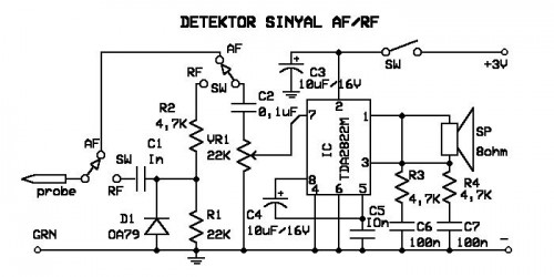
A signal detector circuit designed for detecting signals in both audio frequency (AF) and radio frequency (RF) ranges. This series is compact and straightforward to construct. The signal detector circuit operates by utilizing a combination of components such as diodes,...
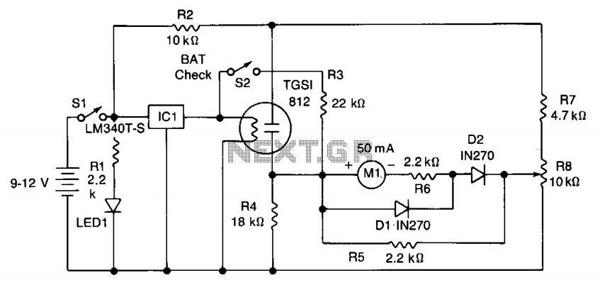
The power drain is approximately 150 mA. IC1 provides a regulated 5-volt supply for the filament heater of the sensor. The gas-sensitive element is connected as one arm of a resistance bridge consisting of R4, R7, R8, and the...