
RF Signal Detector using TDA2822

The signal detector circuit operates by utilizing a combination of components such as diodes, resistors, capacitors, and operational amplifiers to effectively identify the presence of signals. The circuit is capable of distinguishing between AF and RF signals, making it versatile for various applications including audio processing and radio communication.
The core of the circuit typically involves a diode that rectifies the incoming signal, converting it from AC to DC. This is crucial for the detection process, as the rectified voltage can be further analyzed or processed. Following the rectification, a low-pass filter may be employed to smooth the output signal, removing high-frequency noise that could interfere with the detection.
In order to enhance sensitivity and selectivity, operational amplifiers can be integrated into the design. These amplifiers are configured to amplify the rectified signal, allowing for better detection of weaker signals. The gain of the operational amplifiers can be adjusted through feedback resistors, providing flexibility in the circuit's performance.
Additionally, the circuit may include indicators such as LEDs or a meter to visually represent the detected signal strength. This feature is particularly useful in applications where monitoring signal presence is necessary.
The layout of the circuit is designed to be compact, making it suitable for portable applications. The simplicity of the design facilitates easy assembly, allowing both hobbyists and professionals to construct the signal detector with minimal effort.
Overall, this signal detector circuit is an effective tool for identifying AF and RF signals, with a design that emphasizes ease of construction and compactness, catering to a wide range of electronic projects.signal detector electronics that can be used to detect the signal does not AF / RF. This series is very neat and easy to make. 🔗 External reference
Related Circuits
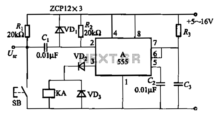
The 555 integrated circuit is utilized in a delay circuit configuration, functioning as a one-shot timer. The delay time can be adjusted using resistor R3 and capacitor C3. Typical values for R3 range from 1 kΩ to 10 MΩ,...

System Oscillator Crystal/Ceramic Oscillator. The following circuit combination of resistors, capacitors, and inductors depicts an equivalent circuit for a crystal or ceramic oscillator. The system oscillator, specifically a crystal or ceramic oscillator, utilizes a combination of passive components, including resistors,...
A Wien-Bridge oscillator circuit can be constructed using the HA2541 operational amplifier along with several basic components. This circuit is capable of generating high-quality sine waves at a frequency of 40 MHz, with a maximum frequency limit of 50...
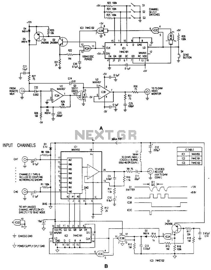
In the video system illustrated in Figures A and R, a single coaxial cable transmits power to a remote location, selects one of eight video channels, and returns the selected signal. This system can choose from several remote surveillance...
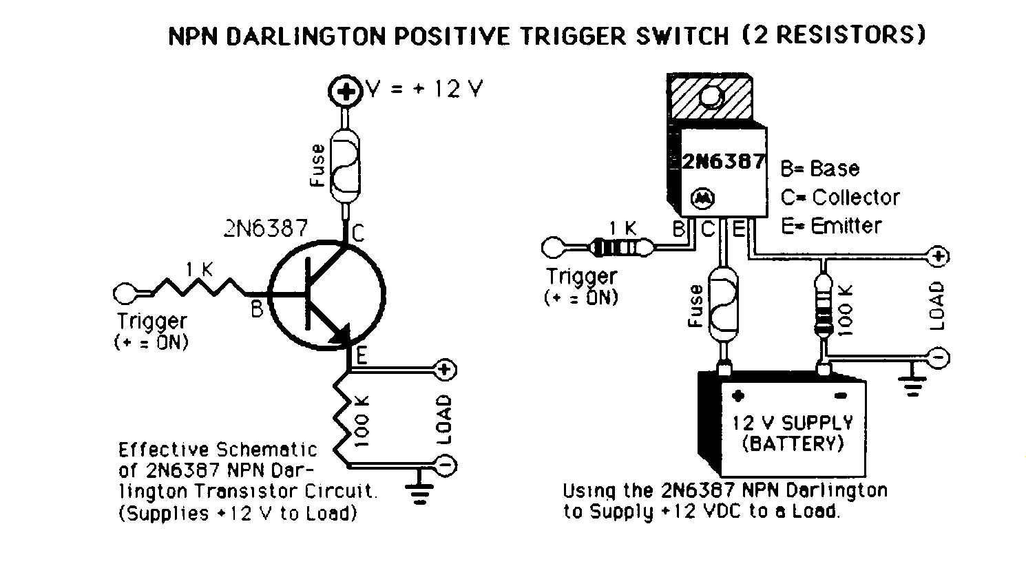
Mechanical 12 Volt DC automotive relays are commonly used in the car audio industry to activate amplifiers, lock doors, and roll up windows. However, solid-state switches provide an alternative method for activating these loads. The reliance on mechanical relays,...
Amplifier circuit featuring a MOSFET output stage, serving as an alternative to the output stage that utilizes bipolar transistors. Advantages of the MOSFET amplifier include ease of operation, the ability to handle hundreds of watts with straightforward parallel configurations,...