
EEG Recording System

This design presents an EEG recording system that amplifies the signal and generates a digital output, which can be connected to an RF chip for wireless data transmission to a base station. The system supports four channels, allowing simultaneous recording of four EEG data streams. The amplifier offers a gain of 100 dB with an input-referred noise of 4.4 µVrms, consuming 72 µW from a 3.3 V power supply. It features a tunable bandwidth to accommodate various signals of interest (e.g., alpha, beta). The amplifier output connects to a delta-sigma A/D converter with adjustable gain and resolution (maximum resolution of 10 bits and maximum gain of 1024). The minimum least significant bit (LSB) achievable with this configuration is 4 µV, aligning with the amplifier's noise level. The sampling frequency depends on the gain and resolution settings of the system.
For biosignal recording, amplifiers must exhibit low input-referred noise and excellent DC rejection. Low noise figures can be achieved through wide input PMOS and large load transistors or by employing a chopper-modulated technique. The former method is well-established, while the latter involves shifting the signal to frequencies above 1/f noise before amplification. Although low noise instrumentation amplifiers have been successfully designed using this approach, it has been avoided here due to its complexities. Instead, a novel technique is utilized to mitigate noise. The operational amplifier (OpAmp) is designed as a two-stage voltage amplifier. Noise analysis of the circuit indicates that the input-referred noise is influenced by the transconductances of the input PMOS, the first stage load, and the second stage transistors. To achieve low noise, it is essential to maximize the width of the input PMOS and the size of the input loads. The second stage transistors contribute minimally to noise, as their contribution is divided by the gain of the first stage. The sizing of the first stage is optimized for superior noise performance, with a bias current (Ibias) set at 8 µA and the second stage transistors biased at 1 µA through specific gate voltages. Additionally, capacitors are integrated between the first and second stages to limit the OpAmp's bandwidth. Clamp transistors in the first stage help minimize transient voltages during slew-rate limiting, reduce common mode gain, and enhance overall noise performance. A straightforward bias circuitry is employed to generate the gate voltages for these transistors, ensuring effective operation of the amplifier.Continuous monitoring of brain activity is essential in understanding neural substrates of many physiological and pathological brain functioning. Low amplitude of EEG signals as well as their noisy nature make it hard to detect them (1-500 uV and.
1-500Hz). Another issue is the DC offset of the signal due to electrode-tissue interface. This DC off set is usually 20-50 mV and 1000 times bigger than the signal. Thus, a very low a noise instrumentation amplifier is required to amplify these signals and remove the DC offset. Typically, electrodes are placed on the scalp of patients and a large number of wires connect to a huge rack of instrumentation amplifiers connected to a computer.
This makes the patient very uncomfortable. Also, the advent of fully implantable microelectrode arrays has created the need for integrated micropower amplifiers. Several chips for EEG or neural recording have been reported in the literature [1]-[5]. [1] introduces a circuit that has a 7. 8 uVrms input referred noise, which is above the signal amplitude. Noise issues are solved in [2] at the expense of relatively large silicon area, 2. 2 mm by 2. 2 mm. [3] and [4] don`t mention noise figures, and [5] uses a BiCMOS process to obtain a low noise amplifier.
Off-chip capacitors are used in some of the designs [6] to reduce noise but they are less suitable for implantable microsystems. Here, we design an EEG recording system that amplifies the signal and produces a digital output that can be connected to a RF chip, so that data can be sent wirelessly to a base station.
The system has four channels so that four EEG data streams can be recorded simultaneously. The amplifier has a gain of 100 db and input referred noise of 4. 4 uVrms, while consuming 72 uW of power form a 3. 3 V power supply. It has a tunable bandwidth so that one can record any signal of interest (alpha, beta, . ). The output of the amplifier is then connected to a delta-sigma A/D converter that has a controllable gain and resolution (Max. Resolution: 10 bits, Max. Gain: 1024). Minimum LSB achievable with this configuration is 4 uV, matching the noise level of the amplifier. Sampling frequency is dependent on gain and resolution of the system. As stated above, amplifiers used for biosignal recording should have a low noise input referred noise and good DC rejection.
Low noise figures can be achieved either by having wide input PMOS and large load transistors or using chopper modulated technique. The former is a well understood method that is first described by [7]. In chopper-modulation techniques the signal is first shifted to frequencies above 1/f noise and then amplified.
Low noise instrumentation amplifiers have been achieved in this way [8], [9] but we avoid this method due to it`s complexities. Here we used a novel technique to over come noise. OpAmp designed is a two stage voltage amplifier (Fig. 1). Noise analysis of the circuit reveals the input-referred noise to be where gm0, gm8, gm13 and gm15 are transconductances of input PMOSes, first stage load, second stage input and second stage load transistors respectively.
thus for having low noise, input PMOS should be wide and input loads should be large. The second stage transistors don`t have much effect on the noise since their noise contribution is divided by the gain of first stage. Sizing of the first stage was done to get a good noise performance. Ibias is 8 uA and the bias current for the second stage transistors was set to 1 uA by "vbias" and "vbiasc.
Aslo this voltage controls bandwidth of the amplifier. Capacitors were added between first and second stage to limit bandwidth of OpAmp. Clamp transistors M35 and M36 in the first stage are used to minimize transient voltages during slew-rate limiting. Also they would help to get lower common mode gain and also improve noise performance. A simple bias circuitry is used to generate gate voltages of these transistors (F 🔗 External reference
Related Circuits
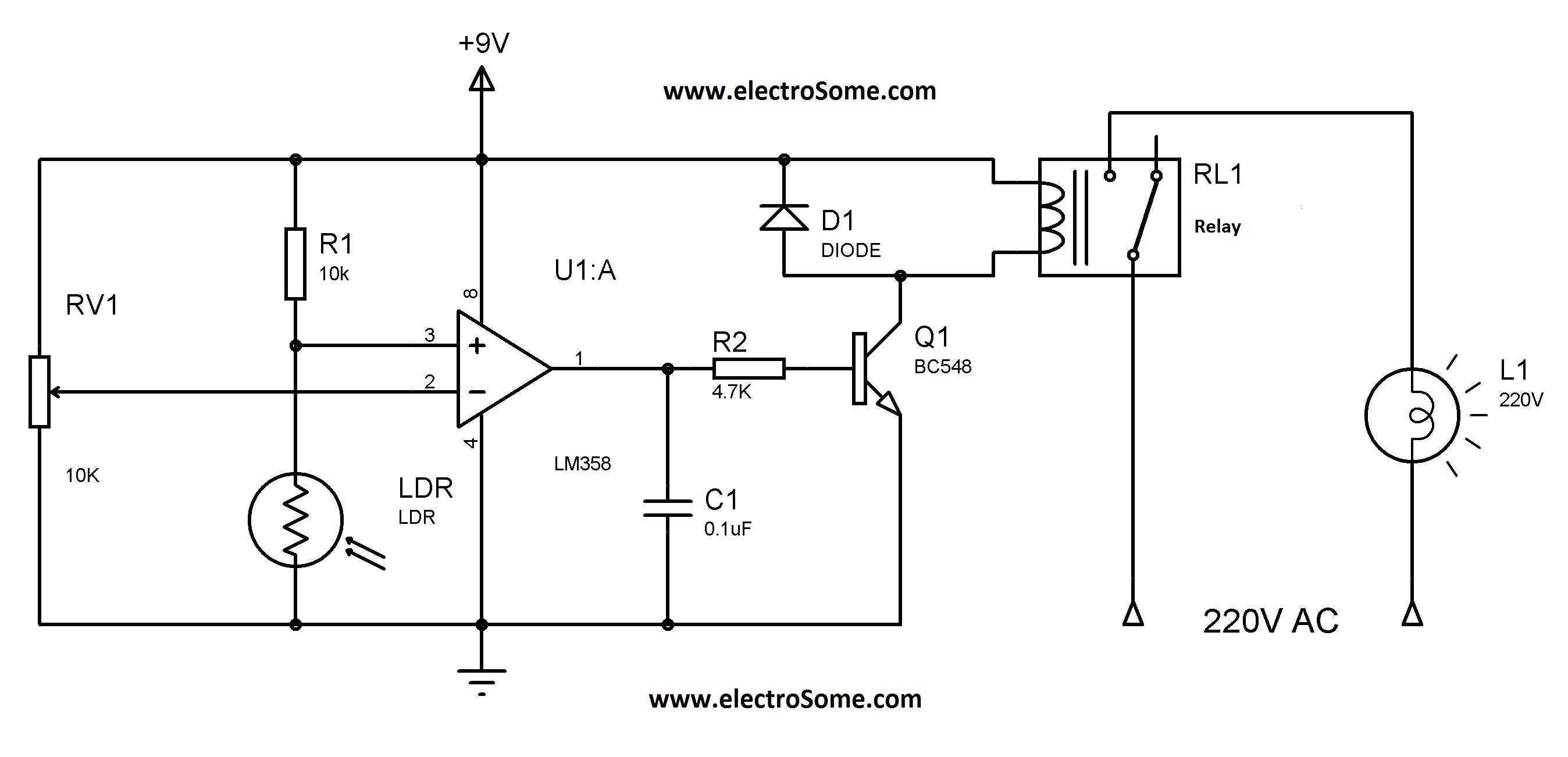
Similar to the previous circuit utilizing the LM358, this design is also cost-effective, priced under 100 rupees. It is a circuit intended for the automatic control of street lights and garden lights. Users do not need to manually turn...
The momentary switch utilized has a safety rating of 10A. If a switch is rated for a current that is too low, the instantaneous current during the first millisecond could cause the switch contacts to fuse together. To achieve...
If a page name is not selected by pressing the button, the previously selected page name continues to be used. The value is stored in EEPROM and may be changed at any time. When the unit is first powered...
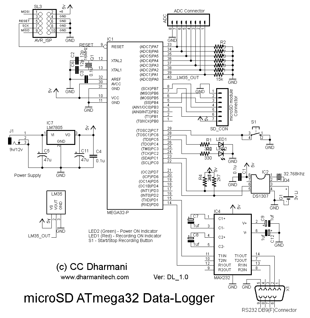
A design example for a portable data acquisition system is provided, which significantly simplifies the circuit design task. The portable data acquisition system is designed to capture, process, and store data from various sensors and input devices. This system typically...
This article discusses the Gadgets, Gizmos, and Arduino (ATMega328). The content is straightforward and informative. The components mentioned in this article can enhance the understanding of the subject. For instance, readers can find and purchase components such as the...
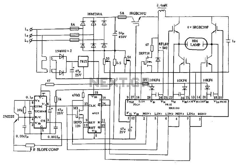
Application of a kilowatt high-pressure mercury lamp ballast system; the schematic in Figure 12.44 illustrates the IR213D used for a high-pressure mercury lamp ballast system. The IR2130 is utilized not only to drive a single-phase full-bridge inverter with four...