Schematic IR2130 for 1kw high pressure mercury lamp ballast system
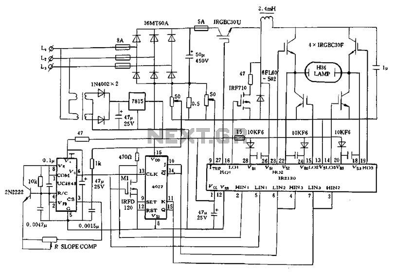
Application of a kilowatt high-pressure mercury lamp ballast system; the schematic in Figure 12.44 illustrates the IR213D used for a high-pressure mercury lamp ballast system. The IR2130 is utilized not only to drive a single-phase full-bridge inverter with four IGBTs but also to manage the high-pressure side. The system begins with a three-phase AC input that passes through a non-controlled rectifier, converting it to a 510V DC voltage. This voltage is then processed by a chopper, which provides a filtered output to the subsequent circuit. The inverter directly drives a kilowatt bulb, operating at an IGBT frequency of 25 kHz. Since a normal working pressure mercury lamp requires a constant current source, the UC3843 is employed to operate in full PWM current-mode. The schematic indicates that the field-effect transistor at the VF pin of the IR2130 operates under negative logic and requires additional components. In this configuration, the capacitance after the chopper filter acts as an output filter capacitor, resulting in an actual input voltage duty cycle of 50% for the full-bridge inverter. A significant advantage of this design is that, despite the IR2130's internal interlocking maximum time of only 2 microseconds, the main circuit operates as a constant current source, preventing damage to the IGBTs even during instantaneous load short-circuits.
The high-pressure mercury lamp ballast system designed around the IR213D and IR2130 integrated circuits incorporates several critical components to ensure efficient operation and reliability. The initial conversion of three-phase AC to 510V DC is achieved through a non-controlled rectifier, which allows for the rectification of AC voltage without the need for control signals. This high voltage is essential for the subsequent chopper stage, which modulates the DC voltage to produce the desired output characteristics for driving the lamp.
The chopper stage plays a crucial role in regulating the output to the inverter. By utilizing high-frequency switching techniques at 25 kHz, the inverter can effectively manage the power delivered to the high-pressure mercury lamp. The use of IGBTs allows for high efficiency and fast switching, which is critical for maintaining the required lamp performance. The UC3843 PWM controller ensures that the current supplied to the lamp remains constant, which is vital for stable operation and longevity of the lamp.
Furthermore, the inclusion of a negative logic configuration for the field-effect transistor at the VF pin enhances the system's flexibility and responsiveness to varying load conditions. The filtering capacitor following the chopper serves to smooth out voltage fluctuations, ensuring that the inverter receives a stable input voltage. This stability is essential for maintaining a consistent output duty cycle, which is crucial for the effective operation of the full-bridge inverter.
Overall, the design of this ballast system emphasizes reliability and efficiency, with protective features that prevent damage to the IGBTs during fault conditions. This approach ensures that the high-pressure mercury lamp operates optimally, providing the necessary illumination while minimizing the risk of component failure.Application ikW high pressure mercury lamp ballast system; Figure 12.44 shows IR213D ikW for a high pressure mercury lamp ballast system schematic. Figure, not only IR2130 is u sed to drive a single-phase full-bridge inverter four I (; BT tube, but is also used to drive the high-pressure side and the crossing is cut, after the three-phase AC input goes through non-controlled rectifier 510V DC voltage, after this chopper chopper and provide after filtering to the subsequent circuit, single-phase output of the inverter direct drive ikW bulb the system, IGBT operating frequency are 25kHz. Since the normal working pressure mercury lamp need a constant current source, it UC3843. to work for full PWM current-mode integrated circuit, the figure, the field effect transistor VF foot IR2130 negative logic work needs to add.
in this system, because the chopper after filter wave capacitance only as iptF, so the full-bridge inverter input voltage actual duty cycle of 50% square crossing. a great advantage of this to bring that although IR 2130 internal interlocking maximum time of only 2-kun, even when instantaneous load short-circuit, but also because the main circuit is a constant current source without burning power IGBT.
