
EI30 Transformer board

The power supply circuit for the DAC and decoder is a crucial component that ensures proper functionality and reliability. The use of a toroidal transformer is advantageous due to its compact size and efficient magnetic performance, resulting in lower electromagnetic interference. The EI transformer, while slightly larger, is also a viable option due to its robust performance in various applications.
The connection terminal X1 is designed for easy integration with a power cable, ensuring a secure and stable connection to the power source. The switch S1 allows for convenient power control, enabling users to turn the system on or off as needed. The inclusion of fuses F1, F2, and F3 serves as a protective measure, safeguarding the circuit against overcurrent conditions that could lead to component damage.
The dual secondary windings from transformer TR1 provide flexibility for different DAC configurations. The ability to connect an S/PDIF decoder through the duplicated output winding S1 enhances the versatility of the design, accommodating various digital audio formats. The choice of fuse ratings is critical; they should be selected based on the expected load current and the specifications of the transformer to ensure optimal protection without nuisance blowing.
The selection of transformers with different secondary voltages allows for compatibility with a range of DACs. For instance, the recommended transformer for the TDA1543 circuit, which requires higher current, must be rated appropriately to handle the load, while ensuring that the voltage output meets the operational requirements of the DAC. The transformer from HAHN with 2x9V secondary windings is ideal for the AD1865 DAC, while higher voltage requirements for other DACs necessitate transformers with different specifications.
In conclusion, careful consideration of the power supply design, including transformer choice, fuse ratings, and overall circuit layout, is essential for achieving optimal performance and reliability in DAC and decoder applications. The described configuration is both practical and effective, utilizing commonly available components to create a robust power supply solution.Every DAC board and also decoder includes power supply part. Only one part which missing is power transformer. It is possible to use for example toroidal transformer with a power switch and fuse holder on a chassis. I offer here one of many variants where is used small EI transformer on the PCB, small fuses on the primary and secondary sides and a
lso small power switch and screw terminals. Circuit includes terminal X1 for connection of power cable. Voltage goes to the switch S1 and via fuse F3 to primary winding of power transformer TR1 with EI30 size. From the transformer goes two secondary windings via fuses F1 and F2 to the output terminals X2 to X4.
Output winding S1 designed for positive voltage rail is doubled for possibility to connect also S/PDIF decoder. Parts are commonly available. Fuses are in a radial variant to the PCB. It is possible to buy a sockets for them. His values coresponds to used transformer and expected consumption. In a case of selecting of DAC with TDA1543 circuit will be current requirements much higher about 500mA and we must select fuses and transformer with a appropriate values.
Transformer with size EI30-2 produces many manufacturers. I choosed transformer from a HAHN company with 2x9V secondary windings which is enough for DAC with AD1865. For DACs with 12V voltage regulators for example PCM1794A we buy 2x15V transformer and for DACs with 8V supply we use transformer with 2x12V secondary windings.
Informations about required voltage we can study on the concrete DAC page. 🔗 External reference
Related Circuits
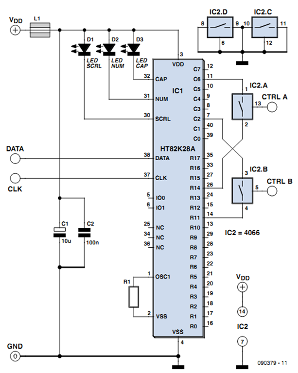
One of the more challenging aspects of creating a control or security system that utilizes a PC, such as a burglar alarm, is connecting the sensors to the computer. This typically requires specialized interface expansion boards, and programming that...
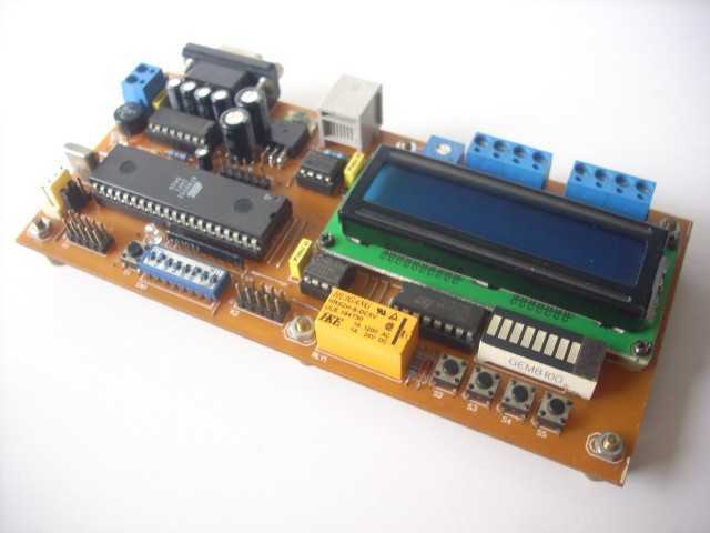
The hardware block is shown in Figure 1. The MCU is 89Sxx microcontroller. And the complete hardware schematic is shown in Figure 2. Port1 is used as data-bus for LCD (4-bit interface, PCB layout for 16x2 character with backlight),...
Channel Relay Board is a simple and convenient way to interface 8 relays for switching application in your project. Input - 12 VDC @ 336 mA. Output - eight SPDT relay. Relay specification - 5 A @ 230 VAC....
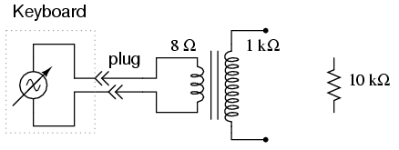
An electronic musical keyboard serves as a source of variable-frequency AC voltage signals. It is not necessary to purchase an expensive keyboard; a model with at least a few dozen voice selections (such as piano, flute, harp, etc.) is...
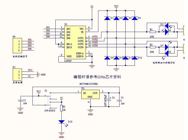
The L298N driver module incorporates the ST L298N chip, commonly utilized to drive two DC motors with voltage ratings between 3V and 30V. It features a 5V output interface that provides power for 5V single-chip circuitry and supports 3.3V...
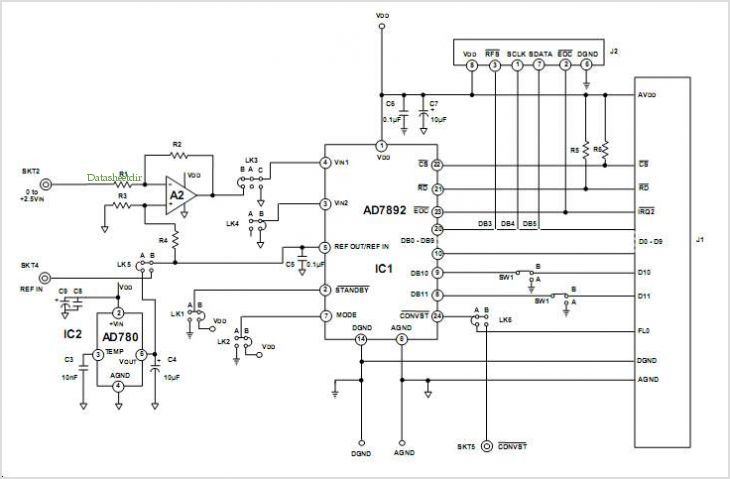
This data sheet describes the evaluation board for the AD9834 direct digital synthesizer (DDS). The AD9834 is a numerically controlled oscillator that utilizes a phase accumulator, a sine look-up table, and a 10-bit DAC. The AD9834 can operate with...