
8 Channel LPT relay board

The Channel Relay Board is designed to facilitate the control of multiple devices through the use of relays, making it ideal for various automation and switching applications. This board features eight Single Pole Double Throw (SPDT) relays, allowing for versatile control of connected devices. Each relay can handle a load of up to 5 Amperes at 230 Volts AC, making it suitable for a range of household and industrial applications.
The board operates on a 12 VDC power supply, drawing a current of 336 mA, which ensures efficient operation while maintaining compatibility with common power supplies. The trigger level for activating the relays is between 2 to 5 VDC, allowing for compatibility with various microcontrollers and low-voltage control systems. This flexibility in trigger voltage makes the relay board suitable for integration into numerous projects, including home automation systems, industrial control systems, and robotics.
Connectivity is simplified through the inclusion of Berg pins, which provide a reliable interface for connecting both the power supply and the control signals. Each relay channel is equipped with an LED indicator that displays the status of the relay, providing immediate visual feedback on the operation of each relay. This feature enhances usability and allows for easy troubleshooting during development and deployment.
For additional convenience, the Power Battery Terminal (PBT) is included, facilitating straightforward connections for relay outputs and auxiliary power sources. This design consideration is particularly beneficial for projects requiring multiple power connections, as it reduces wiring complexity and enhances the overall organization of the circuit.
The PCB dimensions of 169 mm by 72 mm provide a compact form factor, while the four mounting holes with a diameter of 3.2 mm enable secure installation in various enclosures or mounting surfaces. This design aspect ensures that the relay board can be easily integrated into existing systems or custom setups, promoting versatility in application.
Overall, the Channel Relay Board is engineered to offer a robust and efficient solution for controlling multiple relays in a variety of electronic projects, making it a valuable component for engineers and hobbyists alike.Channel Relay Board is a simple and convenient way to interface 8 relays for switching application in your project. Input - 12 VDC @ 336 mA. Output - eight SPDT relay. Relay specification - 5 A @ 230 VAC. Trigger level - 2 ~ 5 VDC. Berg pins for connecting power and trigger voltage. LED on each channel indicates relay status. Power Battery Terminal (PBT) for easy relay output and aux power connection. Four mounting holes of 3.2 mm each. PCB dimensions 169 mm x 72 mm 🔗 External reference
Related Circuits
This is a practical expansion board designed for a PIC development board, intended for DIY use with a 16x2 alphanumeric LCD. The expansion board connects to the PIC development board, providing LCD support, which is essential for numerous projects...
Here's PLL FM transmitter circuit from china. This circuit uses the familiar 2SC1971 for final power amplifier stage. The PLL controller of the FM transmitter use SAA1057 and PIC16F628 (download HEX file). More: If want to change the active...
The ISL97676 can be utilized as an LED driver capable of managing six channels of LED current for TFT displays. This driver supports the operation of up to 78 LEDs with a voltage range of 4.5V to 26V, or...
Timers are widely used in industrial and domestic applications for automating tasks. Microcontrollers can be used to design versatile and accurate timers. Timers play a crucial role in both industrial and domestic environments by facilitating the automation of various tasks....
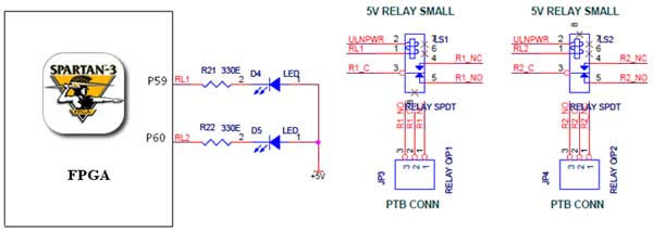
The Spartan-3 board features external 5V relay interfacing, as depicted in the accompanying figure. The ULN2803 is utilized as a driver for the FPGA I/O lines, with the driver outputs connected to the relay modules. A PTB connector is...
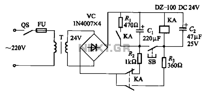
After the turn-off circuit is first applied to the next KA KA, the intermediate interval required is less than Is. This is due to the time needed, which is equal to three times the charge time constant of the...