
Eight PTC phase asynchronous motor protection circuit

The thyristor control circuit operates by utilizing a bridge configuration that effectively manages the temperature of the contactor coil KM. The inclusion of a secondary winding enhances the circuit's ability to provide power protection, ensuring that the system remains stable under varying load conditions. The thermistor (R:., Rt3) plays a crucial role in sensing temperature changes, allowing for real-time adjustments to the control circuit's operation.
The voltage divider, formed by the resistors (Rz, Rs), is essential for establishing the appropriate biasing conditions for the unijunction transistor (VT). This biasing allows for precise control of the switching behavior of the circuit. The diode gates (VDi, VD2, VD3) are strategically placed to facilitate the triggering of the thyristor, enabling it to turn on and off based on the thermal feedback received from the thermistor.
The unijunction transistor's emitter, connected to the bridge circuit, is pivotal in generating the necessary pulse for the thyristor control. This setup ensures that the thyristor operates within its optimal range, providing efficient control over the contactor coil's temperature. The overall design of the circuit emphasizes reliability and responsiveness, making it suitable for applications where temperature regulation is critical.The thyristor control circuit, with the bridge circuit to control the temperature in the contactor coil KM plus a secondary winding wound as a power protection device. R. thermistor , (R:., Rt3) and a resistor R. (Rz, Rs) string associated voltage divider, the diode gates (VDi, VD2, VD3) VT unijunction transistor with the emitter connected in a bridge circuit having switching characteristics.
Related Circuits
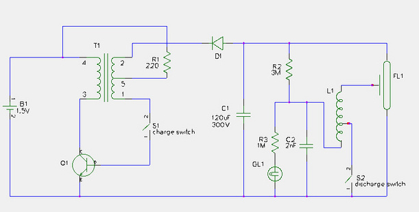
This document provides a step-by-step guide for modifying a disposable camera flash unit to serve as a power supply for a Geiger tube. The process involves removing the flash tube and trigger transformer from the circuit board by gently...
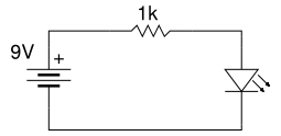
Beginner's Tutorial 1: Building a Circuit on Breadboard - how to build a simple and easy circuit on a breadboard for beginners in electronics. Learn to use an LED and a resistor. This tutorial serves as an introductory guide for...
The first half of the circuit (IC1a) features an input sensitivity of 3 mV and includes a frequency correction network consisting of capacitors C5, C3, and resistors R6 and R8. The bass signal from the phono input is amplified,...
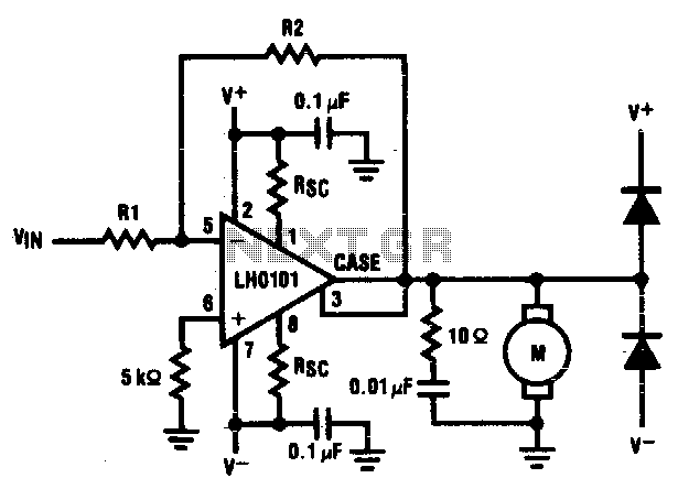
The motor driver amplifier is designed to deliver the rated current to the motor. It is important to manage power dissipation to remain within allowable limits. This precision speed regulation circuit utilizes rate feedback to maintain a constant motor...
The 1-megohm resistor protects the FET from potential damage caused by accidental sparks to its gate lead. The circuit functions adequately without this resistor; however, it is advised not to intentionally apply a charge to the gate wire using...

The circuit operates from a 5-V supply and has a current consumption of 2 mA. The output functions as a current source that can drive or suppress a current exceeding 75 mA with a voltage swing of 4.5 V....