
Hi Fi Stereo Preamp Circuit

The circuit described is a typical audio processing stage, where IC1a serves as the primary operational amplifier. The input sensitivity of 3 mV indicates its capability to handle low-level signals, making it suitable for phono inputs from turntables or other audio sources. The frequency correction network, composed of capacitors C5 and C3, along with resistors R6 and R8, plays a crucial role in shaping the frequency response of the circuit. This network ensures that the bass frequencies are amplified while high frequencies are attenuated, providing a tailored audio output that emphasizes lower frequencies, which is often desirable in music playback.
The switch S1 allows the user to select between different input sources, facilitating versatility in audio signal management. The dual potentiometer configuration, represented by P1 and P2, enables independent control over high and low tone adjustments. This design allows for fine-tuning of the audio output, accommodating various listening preferences and audio characteristics.
The passive nature of the sound control elements within the circuit effectively reduces the risk of overdrive, a common issue in audio amplification circuits where excessive signal levels can lead to distortion. By utilizing passive components for tone control, the circuit maintains a more stable response and minimizes the potential for unwanted clipping or distortion, ensuring a clean and high-fidelity audio output. Overall, this circuit design exemplifies a thoughtful approach to audio processing, balancing sensitivity, frequency response, and user control in a cohesive manner.The first half of the circuit (IC1a) it has an input sensitivity of 3 mV and has a frequency correction composed of C5, C3, R6 and R8. The bass signal coming from phono input is amplified while the high signal is attenuated. The selection of the input signal sources is done with switch S1. P1 and P2 are parte of a double potentiometer. They contro l the high tones and bass. There is no risk of overdrive in circuit due to the passive nature of the sound control. 🔗 External reference
Related Circuits
The Wien-Bridge oscillator meets specific requirements due to the presence of a low-pass filter, a high-pass filter, and a 180-degree phase shift from the feedback networks connecting the input to the output. This configuration results in a total phase...
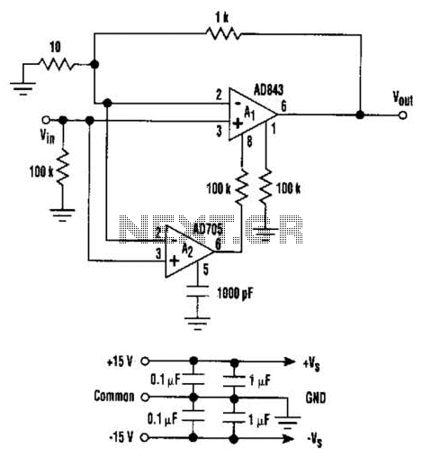
This circuit combines the advantages of low input offset voltage and drift without compromising the overall dynamic performance of the system. When compared to a standalone FET input operational amplifier, the composite amplifier circuit demonstrates a 20-fold improvement in...
This circuit is a small +5V power supply, which is useful when experimenting with digital electronics. Small inexpensive wall transformers with variable output voltage are available from any electronics shop and supermarket. Those transformers are easily available, but usually...
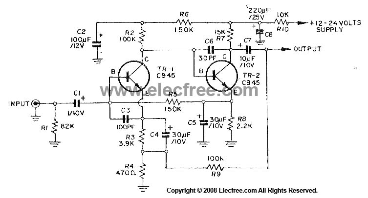
This circuit utilizes three transistors (2SC945, 2C1815, or 2SC828) as the primary components, functioning as a typical low-noise transistor amplifier. It offers a gain of approximately 200 to 300 times and has a frequency response ranging from 50Hz to...
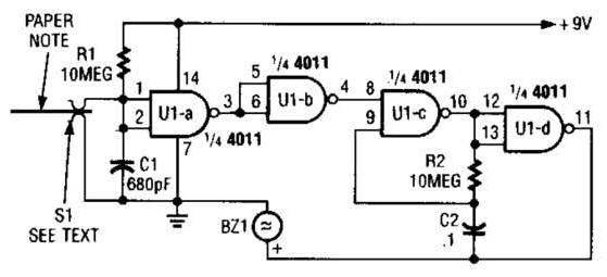
This device prevents paper notes and memos from being overlooked. A paper note placed between two fingers made of a conducting material (metal or conductive plastic) breaks the circuit, allowing pair 1 of Ul-a to go high. The goal...
Construct an accurate LC Meter (Capacitance Inductance Meter) to facilitate the creation of coils and inductors. This LC Meter is capable of measuring very small inductances, making it an ideal tool for various RF coil and inductor applications. The...