
Electric Heater Thermostat

The described circuit utilizes a sensor placed at a distance from the heating element, ensuring accurate ambient temperature readings rather than direct heat measurements. This configuration is particularly beneficial for applications like drying ovens, where consistent temperature regulation is critical. The replacement of mechanical thermal switches with this electronic solution addresses reliability issues, particularly the tendency for contacts to pit and weld, which can lead to overheating and potential safety hazards.
The coarse and fine temperature adjustments provide flexibility in controlling the heating element's output. The use of a trimpot for coarse adjustments allows for a broad range of settings, while the standard potentiometer for fine adjustments enables precise control. The insulated design of the knobs and shafts is an essential safety feature, minimizing the risk of electric shock during operation.
For power control, the choice between a potentiometer and a resistor provides versatility in design. The triac option is suitable for applications where slight inefficiencies are acceptable, whereas the relay-based circuit ensures maximum efficiency, making it ideal for applications requiring consistent performance.
The hysteresis resistor plays a crucial role in controlling the on/off cycling of the heater. By adjusting this resistor, one can fine-tune the temperature differential, ensuring the heater does not cycle too frequently or remain on longer than necessary. The specified resistance range allows for customization based on the specific heating requirements of the environment.
In summary, this electronic circuit design offers a modern, efficient solution for temperature control in heating applications, with built-in safety features and flexibility in operation. The use of reliable components and careful consideration of design parameters ensures a robust and effective heating control system.One Advantage of these two units is the Sensor can be placed Away from the heater, therefore sensing the Actual Room temperature, not the direct heat from the heater. These can also be used in a confined space with a Heat Lamp, to create a Drying Oven. This First Circuit was designed by me to replace the Mechanical Thermal Switches used in some El ectric Heaters I have. The Electrical Contacts on these Mechanical Thermal Switches are getting pitted and are "No Longer Reliable". They could quite easily weld together, keeping this heater on Full. THAT IS DEFINATELY NOT GOOD! The Coarse Temperature Adjustment is a Trimpot on the Circuit Board, set to give a nominal range when using the Fine Adjust.
The Fine Temperature Adjustment is a Standard Potentiometer with a Insulated Knob and/or Shaft to provide electrical protection against electric shock. Using this control you can set the harter to automatically turn "On and Off", Automatically Regulating the Room`s Temperature.
The Power Control for the Triac should be a 2 Watt Potentiometer, Also with a Insulated Knob and/or Shaft to provide electrical protection against electric shock. Or it can be a 2 watt resistor on the circuit board, set for an appropriate heat level. "Typically Full On", as that would be the Normal setting, when using the Mechanical Contacts. On the Schematic, I show a 10 Meg Hysteresis Resistor. This may be made Lower or Higher depending on how many degrees difference you want between On and Off cycles.
Values between 100 K-Ohms and 22 Meg-Ohms are acceptable. The Disadvantage of a Triac is you will Not get 100% Efficiency. This Second Circuit is Simular in design, but uses a Conventional Relay. This will effectively give the 100% Efficiency. Even though the Schematic shows a 2N3904, I used a 2SD401A. Almost Any NPN Transistor is Acceptable. And other than a Power control, The Adjustments are the same as above. 🔗 External reference
Related Circuits
This circuit utilizes a photoelectric coupler to achieve 100GΩ isolation between a TTL (Transistor-Transistor Logic) circuit and a relay circuit. This configuration effectively prevents relay noise and peak voltage from affecting the TTL circuit. When the TTL input signal...
Implementing tactile (haptic) feedback in consumer electronic devices enhances the user experience by providing a sense of touch in user interface design. It represents the latest major interface innovation in smartphones and other portable consumer electronic devices. Various haptic...
A recent thrift shopping experience revealed a toy that appears to be suitable for circuit bending. The toy was found without batteries, preventing any testing at the store. It may be beneficial to bring batteries during future visits or...
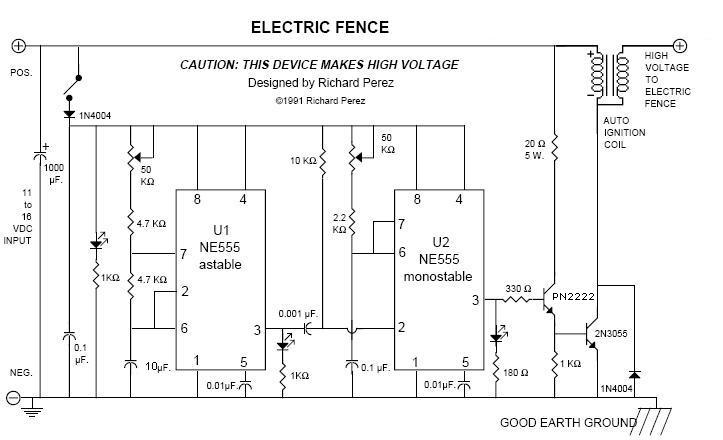
An electric fence perimeter protection circuit designed to operate on batteries and provide configurable pulses of up to 20 kV to safeguard a tent perimeter against bears or other wildlife in the outdoors. The device utilizes two 555 timer...
Over time, various factors can lead to electrical issues in a Mustang. Components may become old and worn, or a wire might rub against something, exposing it to metal. Instances have been observed where body shops inadvertently crimp wires...

This unit is designed to interface TV sound, videotape sound, and 5.1 DVD sound to a 4 channel home theater system. It provides the following functions/options: Mix DVD center into front left/right for Phantom Center effect with optional boost...