
Electric Fence 20KV pulses for perimeter defense

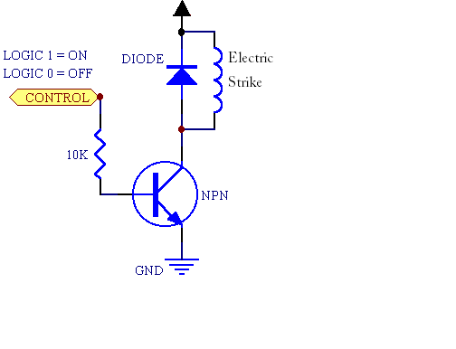
The electric fence circuit is primarily built around the 555 timer IC, which operates in astable mode to produce a continuous square wave output. This output is then used to drive a power transistor that activates the induction coil, generating high voltage pulses. The design allows for flexibility in pulse frequency and width, achieved through the adjustment of the potentiometers. This capability is crucial for tailoring the electric fence to the specific needs of the environment and the desired level of deterrence against wildlife.
The enclosure for the circuit is designed to be waterproof, ensuring durability and reliability in outdoor conditions. The use of AA batteries provides a convenient and accessible power source, but care must be taken to ensure that the battery pack is securely connected and that the voltage remains stable throughout operation. The choice of a VW Bosch induction coil is significant, as it must be capable of producing the required high voltage output while maintaining a suitable current level for effective operation.
For optimal performance, the high voltage output should be connected to a metallic wire loop that is properly insulated to prevent accidental grounding. The grounding of the cold output is equally important, as it provides a return path for the current and enhances the effectiveness of the electric fence. The depth and quality of the ground connection can significantly affect the circuit's performance, particularly in challenging soil conditions.
In troubleshooting, if the circuit does not function as expected, it is essential to check all connections and components for integrity. Testing each resistor and verifying the functionality of the 555 timers and transistors can help identify issues. The use of a flyback transformer is discouraged, as it may not provide the necessary voltage and current characteristics for this application. If adjustments do not lead to improvement, revisiting the circuit design and component specifications may be necessary to ensure compatibility and performance.An electric fence, perimeter protection circuit, designed to run on batteries, and provide configurable pulses of up to 20KV, to protect a tent perimeter against bears or other animals, out in the wild. The device uses two 555 timer circuits to generated a variable frequency, variable width pulses, that are used to drive an auto induction
coil. For my design I`ve used a VW Bosch induction coil with excellent results. The power is provided by 8 AA 1. 5V batteries, connected in series for 12V. The frequency and the pulse width can be adjusted using two potentiometers. The frequency specifies how often will the high voltage pulses be generated and so fed into the perimeter wire, while the pulse width influences the amount of energy fed into the coil, and so how much high voltage energy will be sent into the wire (more energy, more painful the discharge will be). The circuit, the batteries and the induction coil are enclosed in a waterproof plastic recipient. The high voltage output should be connected to a loop of metallic wire placed around the protected perimeter.
This high voltage line should be insulated from ground (use some plastic for that). The cold output should be connected to a good ground: insert a 50cm steel pipe or wire into the ground. Rocky soils or dry soils need a better ground (use a longer wire and bury it as deep as possible). Note: The circuit will not work well with a flyback transformer used instead of the induction coil. A good quality induction coil is a must for this device to work as expected. If testing the output, make sure you set the device to minimum power, by adjusting the pulse width. The shocks at higher power are painful! thank you very much for the link! Fantastic! I was able to get the PCB diagram. One question though, this PCB diagram as you face it is the under part of the (copper side) of the board Right Also would you have any suggestion as how I could efficiently print or transfer this diagram to the copper side of the PCB without losing detail Im just a beginner in electronics this would be my second major project.
I was able to build me a variable voltage regulator (dc) in the past. Now Im excited in creating your idea. Again thank you very much. Then remove the paper and while keeping an eye on it, draw the connections between holes, using some resistant paint or lacquer and a sharp brush or any other tool you`re comfortable with. I built this circuit, to use to energise a fence to protect some beehives. Unfortunately it is not functioning properly. There appears to be no pulse action at all, no matter what the position of the pots. When switching the board off, I get a spark, approx 5-7 mm. The main power transistor gets very hot if the power is left on. So I am not sure if there is an obvious explanation. I was very careful in wiring it up, but perhaps something is wrong. I tested all resistors with a meter as I installed them, so I know they are all correct. There is no specification given for some of the components, even in Perez`s original article in Home Power.
(I got mine from Digi-Key). So this is a bit of an unknown, although I believe what I have should be fine. I guess I have to start over. It took me quite a while to assemble. I am working on this project and I am not getting the sparks. Do I need VW Bosch coil only 8AA 1. 5V does this type of batteries are available in the market Please give me the details about the batteries as early as possible. the flyback transformer produces high voltage but low current, you would need to rectify it and place a capacitor in parallel on the output, to get a shock.
something similar can be seen here: I built your 20kv electric fence circuit which works very well except - every two or three minutes, the 2nd 555 (U2) goes u/s. Now I did use a Mosfet in place of the 2N3056, driven directly from the 555 via a 330 OHM resistor, i.
e. did not use a PN2222 in between the 🔗 External reference
Related Circuits
Electrical lines that include lighting circuits originate from the main distribution panel of the installation. Each line consists of three conductors: phase, neutral, and ground. All three conductors extend to the terminal point of each luminaire, and if the...

The resistance of the CDS cell decreases when exposed to light, activating the 2N3904 relay driver. The circuit utilizes a Cadmium Sulfide (CDS) photoresistor, which is a light-dependent resistor that changes its resistance based on the intensity of light...
A fingerprint door lock system is being considered for implementation. The primary component is a fingerprint reader that, upon recognizing a valid fingerprint, will instruct an Arduino microcontroller to activate a locking mechanism for a predetermined duration. The locking...

When the infrared receiver tube PH302 receives a signal from the remote control, the CX20106A selected frequency amplifier outputs a low-frequency signal. The low-level signal charges capacitor C through diodes D and R, causing the negative side potential of...
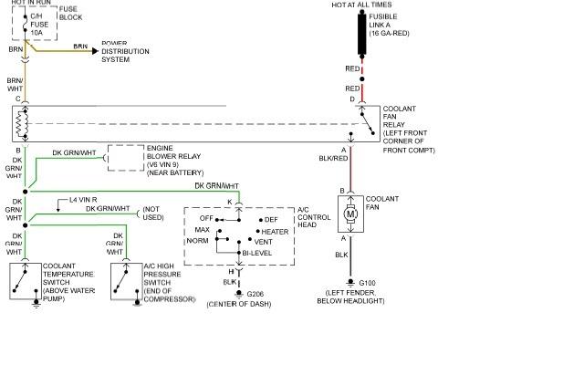
The following page outlines detailed information and the schematic of the 1985 Pontiac Fiero Wiring Diagram and Electrical System. The electrical system consists of: The 1985 Pontiac Fiero features a complex electrical system designed to support various components and functionalities...

The Raspberry Pi offers general-purpose digital input/output pins, known as GPIO pins, which can be utilized for reading digital logic signals or outputting digital logic levels. Although the output current capability is limited, these pins can effectively drive devices...