
Electrical Print Reading

In electrical engineering, diagrams play a crucial role in the maintenance and troubleshooting of circuits. The utility of schematic diagrams lies in their ability to abstractly represent the function and interconnection of components without requiring a detailed physical layout. This abstraction allows technicians and engineers to quickly understand the operational flow of electricity through a system, facilitating repairs and modifications.
The combination ladder and wiring diagram of a reduced voltage motor starter serves as an excellent example of how schematic diagrams can simplify complex electrical systems. By grouping related components, such as power delivery elements and control interfaces, the diagram enhances clarity and reduces the potential for errors during maintenance tasks. The right side of the diagram focuses on the power delivery section, clearly illustrating the input power lines and the series resistors that manage voltage levels during motor startup. This is critical in applications where motor protection is paramount to prevent damage from excessive voltage.
On the left side, the control section showcases essential components such as pushbutton switches and relay coils. The inclusion of these elements highlights the control logic of the motor starter, where user inputs and automated controls interact to operate the motor efficiently. The use of schematic symbols for each component standardizes communication among engineers and technicians, ensuring that everyone can interpret the diagrams consistently.
Transformers, rectifiers, fuses, and circuit breakers are vital components in electrical systems, each serving specific roles that enhance the safety and functionality of the circuit. Transformers adjust voltage levels, which is essential for compatibility with various devices and safety standards. Rectifiers convert AC to DC, allowing for the use of DC-powered devices and systems. Fuses and circuit breakers provide critical protection against electrical faults, preventing damage to both the circuit and connected equipment.
Switches, while seemingly simple, come in various designs and functionalities, each tailored to specific applications. The distinction between different types of switches often lies in their operational features, such as the number of contacts, the method of actuation, and the load they can handle. Understanding these nuances is essential for selecting the appropriate switch for a particular application, ensuring reliable and safe operation.
Overall, schematic diagrams are indispensable tools in the field of electrical engineering, providing a clear, standardized method for representing complex systems and facilitating efficient maintenance and troubleshooting processes.The diagram is useful when replacing components since it shows component locations. It also identifies the wires by certain colors and identifies the specific component terminals that the wires are connected to. The most common types of diagrams are connection ladder, and wiring. Each type is best suited for certain purposes or aspects of maintenance of electrical equipment. Ladder and wiring diagrams are both referred to as ``schematic diagrams`` or just ``schematics``. ``Schematic`` diagrams are somewhat abstract and less pictorial than connection diagrams. They may or may not indicate exactly where the components and wires are physically located, but they will always show the current path between components and they will symbolically indicate the function of each component. ```Figure 2``` is a combination ladder and wiring diagram of a ``reduced voltage motor starter. ``It does not resemble the actual equipment in any way. However, tracing our circuits on it is much easier than on a connection diagram, since components with related functions are usually grouped together.
In ```Figure 2```, the ``input ``power lines (L1, L2, and L3) and the components that conduct electrical energy to the motor are shown on the right side of the diagram. This portion of the diagram also shows the ``series resistors`` (R1, R2, and R3) that reduce voltage to the motor during startup.
The ``control ``section and its various components are shown on the left side of the diagram. Included in this section are the ``pushbutton switches`` (PB1 and PB2), ``relay coils`` (M1, TR1, and CR1) and associated ``contacts``, ``fuse``, and ``step-down transformer. ``M1 is a magnetic motor starter coil, TR1 is a timer relay, and CR1 is a contactor coil. In this article, we begin with the building blocks and basic elements used to create diagrams, and in fact represent functional components, circuits, equipment, and systems.
These elements are called `````schematic symbols`````. ``Transformers`` are used to step voltage up or down, isolate various types of panelboard meters from high voltage sources, and provide low voltage to control circuits. ```Figure 3``` shows the most common transformer symbol. ``Rectifiers`` or ``Diodes`` (```Figure 4```) are primarily used to convert alternating current (AC) into direct current (DC).
The most common applications are DC low voltage control circuits, DC power supplies, and battery chargers. The arrowhead represents the ``anode`` and the vertical bar represents the ``cathode``. ``Fuses ``and`` circuit breakers`` are short-circuit and overload protection devices. Most often they will be found in series with the incoming power source or as the first device in a circuit it is designed to protect.
Fuses (```Figure 5```) incorporate a special low-melting point element that opens to interrupt circuit current in case of a short-circuit or overload. Circuit breakers (```Figure 6```) may have both a ``thermal section`` to open the circuit when current is too high for too long and a ``magnetic section`` to open the circuit immediately to protect against short-circuit damage.
``Thermal overload elements`` (```Figure 7```) can be part of a circuit breaker or a separate device. They are frequently found in the input power lines to motors. The basic purpose of any ``switch`` is to interrupt or close a circuit. However, there are numerous types of switches with various features. The features that distinguish one switch from another will usually determine its application. Some of the distinguishing features are: A switch must have at least two contacts. 🔗 External reference
Related Circuits
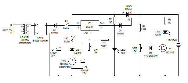
Battery charger utilizing solar and electrical power with a circuit diagram. This dual power source battery charger can charge a lead-acid battery using two different power sources. The battery charger circuit is designed to efficiently charge a lead-acid battery by...
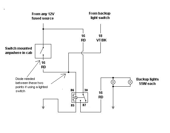
Utilizing a relay allows for a reduction in the length of thick wires that need to be routed, particularly through the firewall and beneath the dashboard. This approach also minimizes the necessity for a larger switch. However, when integrating...
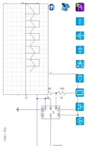
A compilation of the best free Android applications for electronics and electrical engineers, including simulators, resistor color code tools, and electronic toolkits. The compilation of Android applications for electronics and electrical engineers serves as a valuable resource for professionals and...
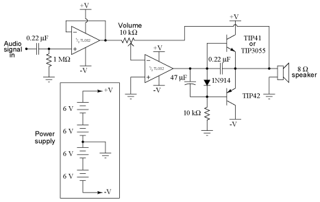
It is advisable to obtain TIP41 and TIP42 transistors, which are closely matched NPN and PNP power transistors with dissipation ratings of 65 watts each. If a TIP41 NPN transistor is unavailable, the TIP3055 (available from Radio Shack) serves...
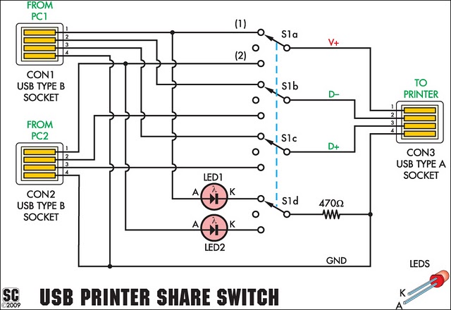
This device allows two computers to share a single USB printer or other USB devices, such as an external flash drive, memory card reader, or scanner. A rotary switch is used to select the PC that will use the...
The core component of this controller is a switch mode voltage converter. L1 is responsible for converting voltage, while Q1 acts as the switch that controls the current flowing through L1. The switch mode voltage converter operates by rapidly switching...