
Universal High-Power LED Driver with 3D-printable Case

The switch mode voltage converter operates by rapidly switching the Q1 transistor on and off, allowing energy to be stored in the inductor L1 during the on phase and releasing it to the output during the off phase. This process enables efficient voltage conversion, which is essential for applications requiring stable output voltage levels despite variations in input voltage or load conditions.
Inductor L1 plays a crucial role in energy storage and transfer. Its inductance value must be carefully selected to balance the converter's response time and efficiency. The switching frequency, determined by the control circuitry, influences the size and choice of L1, as higher frequencies allow for smaller inductors but may also introduce higher losses.
Transistor Q1, typically a MOSFET or IGBT, must be chosen based on its switching speed, voltage rating, and current handling capability. The gate drive circuitry is essential for ensuring that Q1 switches efficiently, minimizing transition losses during the on/off cycles.
Additional components in the circuit may include diodes for rectification, capacitors for filtering, and feedback mechanisms for regulating the output voltage. The feedback loop monitors the output voltage and adjusts the duty cycle of the switching signal to maintain the desired output level, thereby enhancing the stability and performance of the voltage converter.
Overall, the switch mode voltage converter design is a critical aspect of modern power supply systems, providing high efficiency and compact solutions for a wide range of electronic applications.The heart of this controller is a switch mode voltage converter. L1 converts voltage. Q1 is the switch that control current the goes through L1. The b.. 🔗 External reference
Related Circuits
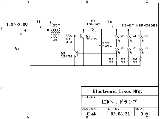
This is a practical white LED head mount lamp (flashlight). Recently many white LED flashlights appear on the market. However, most flashlights require three cells because they are regulating output current with only series resistor. The odd number of...
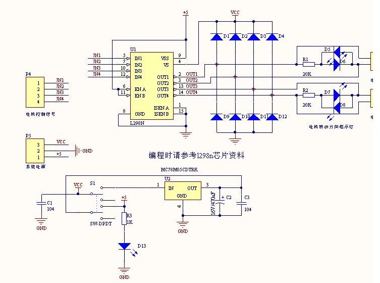
The L298N driver module incorporates the ST L298N chip, commonly utilized to drive two DC motors with voltage ratings between 3V and 30V. It features a 5V output interface that provides power for 5V single-chip circuitry and supports 3.3V...
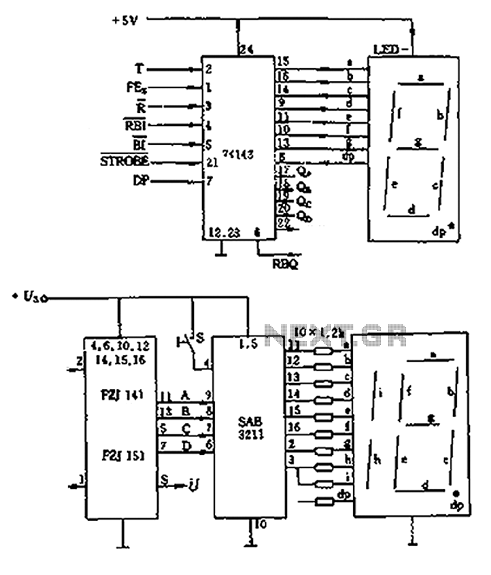
The decimal seven-segment storage decoding drive unit 74HC143 provides a constant output for all segments, each at a voltage of 5V and a current ranging from approximately 15mA to 22mA. The BCD data for the seven-segment decoder can be...
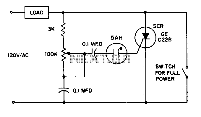
The 5AH will trigger when the voltage across the two 0 µF capacitors reaches the breakdown voltage of the lamp. Control can be obtained from full off to 95% of the half-wave RMS output voltage. Full power can be...
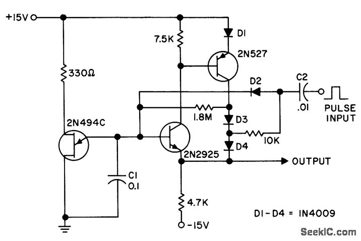
The circuit features high input impedance and low output impedance, which minimizes voltage droop between pulses. A staircase waveform is generated by the combination of diode D2 and capacitor C2, which is bootstrapped on the output to ensure equal...
This LED flasher circuit is similar to the previous transistor-based LED flasher but utilizes a 555 integrated circuit as the primary component. The schematic diagram illustrates an LED flasher circuit that produces alternating LED flashing, with distinct flashing periods...