
Electromagnetic Ring Launcher Circuit

The electromagnetic ring launcher circuit is a sophisticated assembly designed to illustrate the principles of electromagnetic propulsion. The clock circuit, centered around the U5 component, operates as an astable multivibrator, generating a continuous square wave signal. This signal serves as the timing reference for the subsequent subcircuits. The countdown/display circuit is critical for user interaction, featuring the U3 synchronous up/down counter, which counts down from a preset number of seconds to launch. Its BCD outputs are processed by the U4 ECG8368, which converts the binary-coded decimal data into a format suitable for display on the common-cathode seven-segment display (DISP1).
The trigger circuit is essential for initiating the launch sequence. It utilizes the MOC3010 optoisolator to safely isolate the control logic from the high-power components. The output of the optoisolator drives the TR1 Triac, which handles the high current required to energize the repulsion coil (L1). The repulsion coil generates a magnetic field that interacts with the metal ring, creating a force that propels the ring along its path.
The reset circuit is designed to ensure that the system can be easily reset between launches. It employs the U1 NAND gate to manage the reset logic, while U2 acts as a monostable timer, providing a controlled pulse to reset the countdown and prepare the system for the next launch sequence. The integration of these components allows for a smooth operation, demonstrating the principles of electromagnetic repulsion effectively. Overall, the design emphasizes safety, functionality, and user interaction, making it an educational tool for understanding electromagnetic principles. The electromagnetic ring launcher is comprised of.four subcircuits: a clock circuit (built around U5, a 555 oscillator/timer configured for astable operation), a count-down/display circuit (built around U3), a 74190 synchronous up/down counter with BCD outputs that is configured for countdown operation; U4, a ECG8368 BCD-to-7-segment latch/decoder/display driver; and DISP1, a common-cathode seven-segment display), a trigger circuit (comprised of U6), an MOC3010 optoisolator/ coupler with Triac-driver output; TR1, an SK3665 200-PIV, 4-A Triac; and a few support components), and a reset circuit (comprised of Ul, a 7400 quad 2-input NAND gate; U2, a second 555 oscillator/timer configured for monostable operation; and a few support components). This circuit is that of a repulsion coil (LI) used to demonstrate the principle of electromagnetic repulsion by propelling a metal ring around the core of LI through the air.
A countdown circuit is provided to count seconds before launch.
Related Circuits
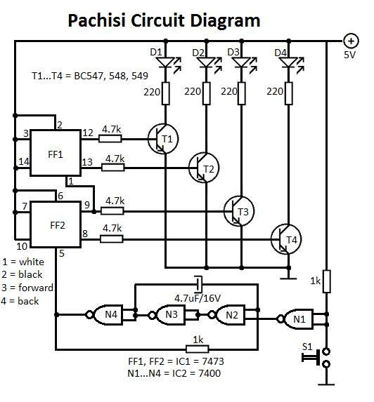
The Pachisi game is designed for two players. Each player has one figurine, which is initially placed on positions indicated by arrows on the game board. The Pachisi game, often referred to as the "Royal Game of India," is...
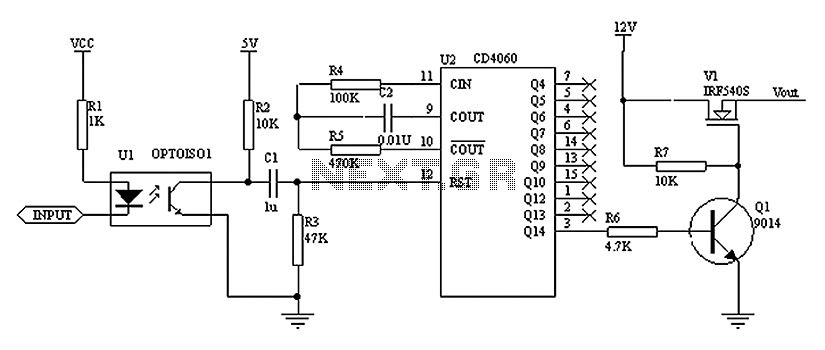
As shown in the figure, the operation of the circuit relies on the timing of the reset pulse to the CD4060. This ensures that the state is finalized in Q1, allowing the NMOS transistor to control the LED, keeping...
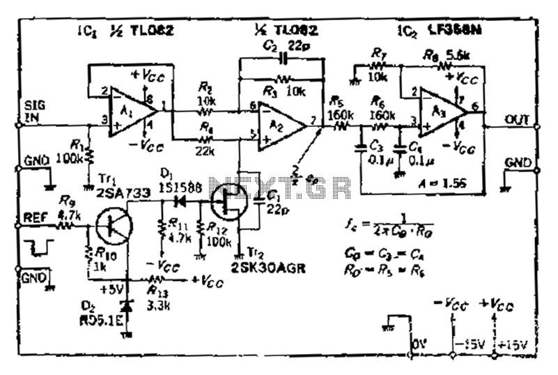
After turning off TT2, the input signal enters through chi Az, where the input resistance is very high and reaches the same potential. The inverting input terminal must also be associated with this movement. Therefore, Trr functions as a...
The application that we propose is a simple filter that limits the acoustic region (20-20000Hz) to the region 20-100Hz. With the manufacture proposed, an active filter can be created to drive a loudspeaker for very low frequencies. This allows...
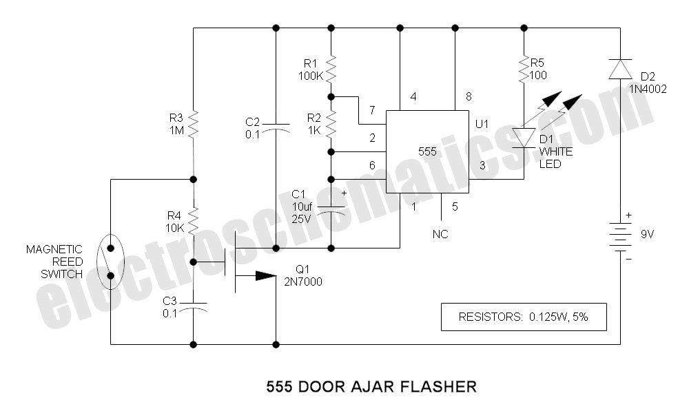
This is a compact LED flasher circuit designed using the 555 timer integrated circuit (IC), powered by two 1.5V batteries. The circuit can function as a flashing metronome, dark room timer, reminder, or for other similar applications. In the...
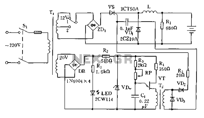
The circuit operates on the principle of a transformer, bridge rectifier, and conditioning for battery charging. The charging current can be adjusted to approximately 12V at 100A. For battery charging, a charging rate of 10 hours requires a charging...