
Electronic Birthday Candle

The second half of the circuit comprises a standard BJT flip flop, a bi-stable circuit that maintains one of two states. In this configuration, either Q2 is on, allowing current to flow through D2 (the LED) while keeping Q1 off, or Q1 is on, which turns Q2 off. Although modeling might suggest the circuit can balance between states, in practice, noise will trigger it to settle into one state. To switch states, a signal must be applied. This flip flop can also be termed a "Set-Reset Latch," where one signal "sets" it to one state and another "resets" it to the other. Typically, low pulses are used for these signals on the transistor bases. When Q2 is on and pulls the base of Q1 low, applying a low pulse to Q2 will turn it off, allowing current through R5 to raise the base of Q1 and turn it on.
In this design, the "set" signal is a high pulse from the envelope follower, applied to the base of the currently off transistor (Q2). Once the pulse reaches about 0.7V (a diode drop), the BJT turns on. Although this method is generally discouraged due to potential instability and excessive power draw from both transistors being on simultaneously, it suffices for this application. The envelope follower's output is directed to the base of Q1 to activate it, with a switch connecting the voltage rail to the base of Q2 to turn it on.
Attention must be paid to resistors R7 and R8, as equal collector loads are essential for the bistable circuit's operation. If R7 is too large, it may not provide sufficient current to keep Q2 on if its collector current is too high. Ideally, the load on each collector should be approximately equal; however, the presence of the LED's diode drop complicates this. With a 3V rail, the current through D2 is about 5mA, leading to the selection of R7 to provide a similar current to Q1's collector. This setup is contingent on maintaining a 3V rail.
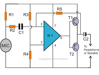
The circuit can be visualized as follows: the microphone feeds into the gain stage, which is followed by the envelope follower. The output of the envelope follower is then connected to Q1's base. A switch mechanism allows the voltage rail to connect to Q2's base. The LED is positioned in series with Q2, ensuring that when Q2 is active, the LED illuminates. The careful balance of resistors ensures that the circuit operates reliably, maintaining the desired functionality of turning off the LED in response to the noise detected by the microphone.So the concept here is pretty simple. I wanted to mount a microphone on a stick with an LED and design a circuit that would react to a large amount of noise on the microphone input (blowing) to turn off the LED. As you might expect, the schematic for this thing is very straight forward. The device is powered by a CR2016 3V coin cell battery which always supplies power to the circuit (there`s no power switch). If left in, even when the LED is turned off, the battery will die, but I figure for something with such a limited one-time use, it was an acceptable requirement. The left side of the circuit is the familiar gain stage/envelope follower that you`ve seen in many of my sound reactive circuits.
I left the low pass filter in (R6 and C7), though it`s not really necessary. The only difference this time is that there is no gain on the microphone. Typically, blowing on a microphone actually clips the mic which means you`re producing the largest electrical signal possible. I experimented with different gain levels until I realized that anything more than 0dB gain caused the candle to be too sensitive and made it blow itself out.
Originally, I was hoping to flex my analog muscles and make a straight up FET gain stage, but I realized that with a CR2016 battery as my voltage source, there would be too much variability on the rail to set a good bias point. The second half of the circuit is a standard BJT flip flop. You probably saw a lot of these in my transistor clock posts. This is a "bi-stable" circuit which means it must always exist in one or two states. Specifically, either Q2 is on and pulling current down through the D2 (the LED) and keeping Q1 off, or Q1 is on which keeps Q2 off.
If you try modeling a circuit like this, you might find that it can balance between states, but in reality, this never happens as a tiny bit of noise will cause it to fall into one of the two states. So once the flip flop is in a state, you have to apply a signal to flip it to the other state. This type of flip flop can also be called a "Set-Reset Latch" which means that you have a signal to "set" it in one state and then a different signal to flip it to the other state ("reset" it).
Typically with this kind of circuit, these signals are low pulses on the bases of the transistors. Imagine Q2 is turned on and pulling the base of Q1 low. If you were to apply a low pulse to the base of Q2 for a moment, Q2 would immediately turn off. While off, current would begin to pass through R5 and raise the base of Q1 turning it on. I had to change this around a bit because my "set" signal would be a high pulse (the output of the envelope follower) instead of a low pulse. Instead of applying a low pulse to the transistor`s base that is currently turned on, I applied a high pulse to the transistor that`s currently turned off.
Once that pulse hit about 0. 7V (a diode drop), the BJT would turn on. This is generally frowned upon because for a moment, you have both transistors turned on which can cause excessive power draw as well as instability in more complicated circuits, but for my needs, it works fine. So I pass the output of the envelope follower to the base of Q1 to turn it on and have a switch connecting the voltage rail to the base of Q2 to turn it on.
The other thing to watch out for is R7 and R8. In order for a bistable circuit like this to work, the load on the collector of each BJT must be more or less equal. For example, if R7 is too large, it might happen that the current through it is not enough to keep Q2 turned on if Q2`s collector current is too big.
Nominally, you`d want the load on each collector current to be a resistive load of approximately equal value, but I didn`t have this option as I had an LED`s diode drop on one side. With a 3V rail, the current through D2 will be about 5mA ( ), so I chose R7 to provide approximately that much current to Q1`s collector.
This will only work if the rail is 3V. 🔗 External reference
Related Circuits

This smoke detector electronic project is designed using the LM1801 and common electronic components. The smoke detector circuit diagram does not utilize ionization detection, gas sensors, or optocouplers; instead, it employs two photoresistors (LDRs) and an LED. The circuit...
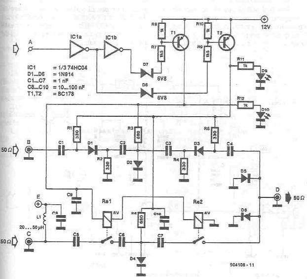
This antenna selector circuit diagram electronic project is constructed using standard electronic components and facilitates the switching between two FM antennas through a logic signal. The gates IC1b and IC1a manage the switching and interface between the required logic...
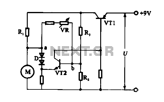
The electronic circuit for steady speed motor applications utilizes an automatic remote control system to regulate the motor power supply, thereby achieving consistent speed control. The circuit diagram illustrates a DC motor connected to the system. Given that the...
Protect your locker or briefcase from theft using this pocket-sized gadget. It emits a loud police siren to attract attention. The circuit utilizes a single integrated circuit (IC). This circuit is designed to provide a compact and effective security solution...
This document discusses the creation of an electronic spy bug circuit using two methods: one involving a wired connection from the transmitter to the receiver, and the other being a completely wireless setup capable of eavesdropping on conversations up...
The two-tone electronic doorbell circuit consists of an input trigger circuit and an audio output circuit. The input trigger circuit includes a doorbell button (S), a transistor (V1), resistors (R1-R3), a capacitor (C1), and a dual D flip-flop integrated...