
Two-tone electronic doorbell 1

The two-tone electronic doorbell circuit operates by utilizing a combination of analog and digital components to produce distinct audio signals in response to the activation of the doorbell button. When the button (S) is pressed, it triggers the input circuit, which initiates the operation of the transistor (V1). This transistor acts as a switch, allowing current to flow through the resistors (R1-R3) and charging the capacitor (C1).
The dual D flip-flop integrated circuit (IC1) plays a crucial role in generating the two-tone sound. It is configured to alternate between two different output states, each corresponding to a specific audio tone. The outputs A1 and A2 are connected to the audio output circuit, which typically includes an amplifier and a speaker. The audio output circuit is responsible for converting the digital signals from the flip-flop into audible sounds.
The design of the circuit ensures that the two tones produced are distinct and recognizable, enhancing the functionality of the doorbell. The choice of components, such as the specific values of the resistors and capacitor, as well as the characteristics of the transistor, can be adjusted to fine-tune the sound output and response time of the doorbell. Overall, this circuit provides a reliable and efficient solution for a two-tone electronic doorbell system.The two-tone electronic doorbell circuit is composed of the input trigger circuit and audio output circuit, ans it is shown in Figure 3-107. The input trigger circuit is composed of the doorbell button S, transistor V1, resistors Rl-R3, capacitor Cl and dual D flip-flop integrated circuit ICl (Al, A2).
Audio output circuit consists of the audio output circui.. 🔗 External reference
Related Circuits
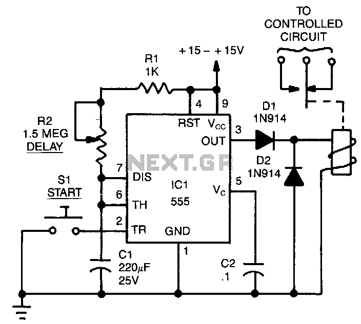
The time delay, T, in seconds is calculated using the formula: T = 1.1 x C1 x (R1 + R2). The resistances are measured in megohms and the capacitances in microfarads. The combined resistance of R1 and R2 should...

AM radio receivers demodulate amplitude-modulated (AM) signals. The primary source of these signals is the Standard AM Radio Broadcast Band, although shortwave stations also utilize AM modulation. Amplitude modulation was developed between 1900 and 1917 by amateur radio enthusiasts....
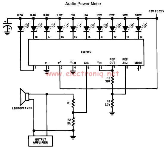
The LM3915 monolithic integrated circuit can be used to design a simple audio power level meter that senses analog voltage levels and drives ten LEDs, LCDs, or vacuum fluorescent displays, providing a logarithmic 3 dB/step analog display. One pin...

Writing about multiple circuits in Marx, an entire new set has been discovered, referred to as "the" Marx Generator. There are diagrams available, along with a useful quote: "The main advantage of the Marx circuit configuration over a more...
The circuit was designed to create a lamp that incorporates the operation of a touch dimmer using the S566B integrated circuit manufactured by Siemens. The circuit utilizes the S566B IC, which is specifically designed for touch-sensitive applications, to enable a...
Diagram 2 depicts a shake tube circuit with a capacitance (C) and a trigger voltage rectifier filter element. The circuit includes a trigger voltage transistor amplifier (H), three pull tubes (n, U, v), and utilizes a thyristor as a...