
Electronic circuitry Dot Award

The circuit operates based on the interaction between two integrated circuits, IC1 and IC2, along with a momentary switch and a capacitor. When the button switch (S) is pressed, it initiates the charging of capacitor C1, which provides the necessary power to IC1. IC1 is designed to function as a pulse oscillator; it generates a series of pulses that begin at a high frequency and subsequently decrease in frequency over time. This behavior is crucial for creating a dynamic visual effect.
The duration of the pulse oscillation is controlled by the charging characteristics of capacitor C1 and the inherent design of IC1. Once the capacitor is charged, the oscillation continues for a predetermined time, typically exceeding ten seconds, before stopping the output pulse. This feature allows for a brief period of activity, which can be utilized for various applications, such as indicating a status or providing visual feedback.
IC2 serves a dual purpose: it counts the incoming pulses from IC1 and decodes these pulses to drive a display comprised of ten LEDs. This arrangement enables the circuit to visually represent the pulse count in a clear and engaging manner. The LED display can be configured to light up in response to the count, creating a sequence that is both informative and visually appealing.
Furthermore, the output from IC2 can be modified to slow down the flashing of the LEDs. This delay mechanism ensures that the visual feedback is not only immediate but also allows for a gradual transition, enhancing the user experience. The design of this circuit is versatile and can be adapted for various applications, including educational tools, decorative lighting, or as a component in larger electronic systems where visual indicators are required.Dot Award ; This circuit is tested and functionable. The circuit consists of two lC constituted. lC1 constitute pulse source, because it is just a momentary button switch S is closed after charging the capacitor C1 to a C1-powered, so IC1 pulse oscillation source composed only been a while (more than ten seconds) will stop the vibration. But it is the first oscillation frequency from high to low. Pulse counting, decoding so constituted by the IC2 and display driver driven ten LED, then also with the pulse IC, output and to slow down after another to stop the flashing.
Related Circuits
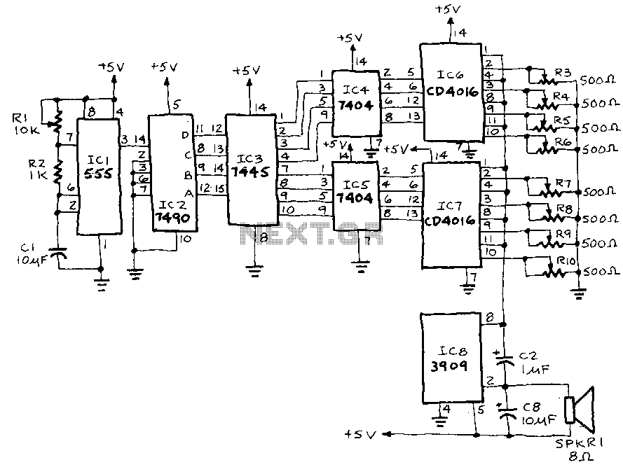
IC1, a 555 timer, is configured as an astable multivibrator to generate a signal that triggers IC2, a 7490 decade counter. This counter produces a BCD output that is connected to IC3, a 7445 BCD-to-decimal decoder/driver. The output from...
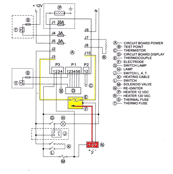
With the exception of pilot-type water heaters and some smaller LP/Electric refrigerators, modern LP appliances in RVs are controlled by electronics. Modern LP (liquefied petroleum) appliances utilized in recreational vehicles (RVs) have largely transitioned to electronic control systems, enhancing their...
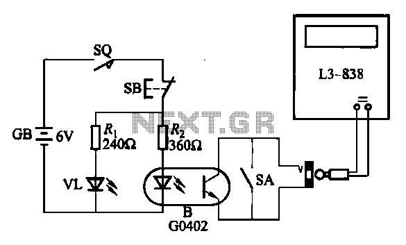
An electronic calculator features an automatic counting interface circuit, as illustrated in the accompanying figures. Figure (a) depicts a stroke switch controlled via optocoupler B. Figure (b) shows the application of a reed switch (KR) for pulse control signals....
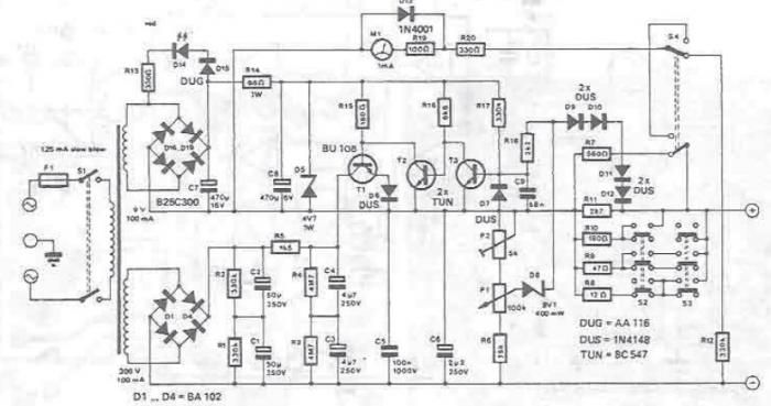
A DC power supply can be designed using high voltage transistors to provide an adjustable supply voltage ranging from 10 to 300 volts, which can be modified with potentiometer P1. Transformers used in these power supplies typically feature multiple...
This project was undertaken in June 1996 as a final year electronics project. The circuit was constructed using individual components, including logic gate integrated circuits (ICs) and a keyboard decoder IC. Since then, electronics has advanced, and if created...
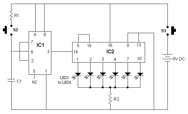
It is advisable to enclose this circuit in a box and label each LED with numbers from 1 to 6. When switch S1 is momentarily pressed, one of the six LEDs will illuminate, with the number corresponding to the...