
Electronic counter with automatic counting interface circuit a

The electronic calculator's automatic counting interface circuit is designed to enhance functionality and reliability in counting applications. The stroke switch depicted in Figure (a) serves as an initial input mechanism, enabling user interaction with the system. The optocoupler B acts as an isolator, ensuring that the control signals from the stroke switch do not interfere with the main circuit, thus maintaining signal integrity.
In Figure (b), the reed switch (KR) is employed to generate pulse control signals. This component operates based on magnetic fields, providing a reliable means of detecting the presence of an object or user action, which in turn generates a pulse that can be processed by the calculator's circuitry. The pulse signal is crucial for accurate counting and is transmitted to subsequent components.
Figure (c) illustrates the dual application of optocouplers B, which are utilized alongside the pulse signal control. The LED (VL) serves as a visual indicator, allowing users to monitor the counting pulse operation in real-time. This feature is essential for debugging and ensuring the system operates as intended, providing immediate feedback on the counting process.
Lastly, Figure (d) showcases the use of a photocell (LD) coupled with a relay (KA) for control functions. The photocell detects light levels and can be used to trigger the relay, which in turn activates or deactivates other components within the circuit. This setup allows for automated control based on environmental conditions, enhancing the versatility of the electronic calculator.
Overall, the integration of these components creates a robust and efficient electronic counting system, suitable for various applications that require precise measurement and control. The use of optocouplers, reed switches, LEDs, and photocells ensures that the circuit remains reliable and responsive to user inputs and environmental changes.Electronic calculator with automatic counting of the interface circuit shown in Figure. Figure (a) stroke switch so via optocoupler B control; Fig. (B) the use of reed KR and p ulse control signal; FIG. (C) the use of optocouplers B and pulse signal control, LED VL to monitor counting pulse operation; Fig. (d) the use of photocell LD and relay KA control.
Related Circuits

The adjustable power supply can be reconfigured by changing the value of V2 and enhancing other components as needed. The output voltage is calculated using the formula Vnm = 1.25 (1 + R2/R^). Additionally, R2 can be modified as...
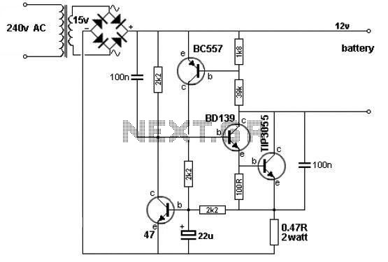
A simple 12V battery charger circuit can be designed using a TIP3055 power transistor to limit the current to the battery. The circuit turns off when the battery voltage reaches approximately 14V or if the current exceeds 2A. This...

This schematic represents a radio receiver circuit based on the TDA7088T, which is suitable for use in mono portable and pocket radios. The TDA7088T is a bipolar integrated circuit designed to operate with a minimal number of peripheral components...
Involvement is a modified version of the classic circuit of automatic level control signal used in tape recorders. The purchase price of the components (using TL072) does not exceed CZK 60 for a channel. For a range of entry...

An electronic circuit consists of individual electronic components such as resistors, transistors, capacitors, inductors, and diodes, which are interconnected by conductive wires or traces that allow electric current to flow. The sine wave or sinusoid is a mathematical function...
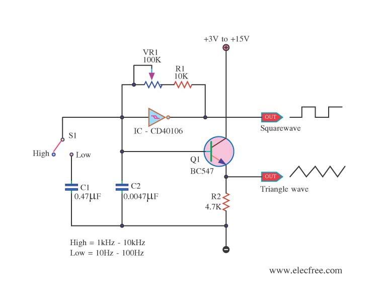
This is a function generator project that can be used as a triangle and square wave generator. The main components include the CD40106, a popular CMOS integrated circuit, and a standard transistor. The function generator circuit utilizes the CD40106, which...