
Electronic Cricket Sound Generator

The electronic cricket circuit is designed to replicate the natural sound of crickets, providing an auditory experience that many find soothing or nostalgic, particularly in urban settings where such sounds are often absent. The circuit typically employs a timer or microcontroller to generate pulse-width modulation (PWM) signals, which simulate the chirping pattern of crickets.
The primary components of the circuit include a microcontroller or timer IC, a piezoelectric speaker or buzzer, and passive components such as resistors and capacitors. The microcontroller is programmed to produce a series of pulses that vary in frequency and duration, mimicking the irregular chirping characteristic of real crickets.
The piezoelectric speaker converts the electrical signals from the microcontroller into sound waves. The choice of speaker is crucial, as it must be capable of producing the desired frequency range to accurately replicate the cricket sound.
Power supply considerations are also essential; the circuit can be powered by batteries for portability or connected to a wall outlet for stationary use. Additional features may include adjustable volume control and the ability to change the chirping rate, allowing users to customize the experience to their preferences.
In summary, the electronic cricket circuit serves as an innovative solution for those seeking the comforting sounds of nature in an urban environment, utilizing a combination of electronic components to recreate the unique auditory signature of crickets.Why an electronic cricket? Many people like the cricket sound specially if they live in a big town. This electronic cricket circuit works in pulses, so the.. 🔗 External reference
Related Circuits

Two CA3130 operational amplifiers are utilized, with one functioning as a multivibrator and the other serving as a hysteresis switch. Additionally, a CA3160 amplifier is employed as a linear staircase generator. The circuit incorporates three BiMOS operational amplifiers. The circuit...
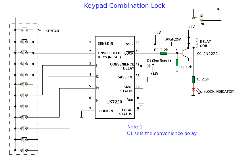
When connected to a ten-digit keypad, the circuit can identify one four-digit combination from a total of 5040 possible codes. Upon entering the correct four-digit sequence from the keypad, the LOCK feature activates while the Lock Status deactivates. The...
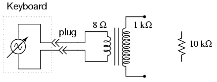
An electronic musical keyboard serves as a source of variable-frequency AC voltage signals. It is not necessary to purchase an expensive keyboard; a model with at least a few dozen voice selections (such as piano, flute, harp, etc.) is...
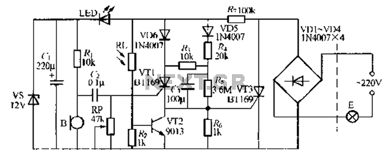
A relatively simple circuit for controlling a stair walkway light with a delay feature. The circuit has a drawback in that the voice activation is somewhat less sensitive, making it sometimes difficult to trigger with general conversation. However, it...

The 12kV High Voltage Generator utilizes a unique adjustment to generate approximately 12,000 volts with a current of about 5 µA. It consists of two SCRs forming two triggering circuit paths. These SCRs discharge a 0.047 µF, 400V capacitor...
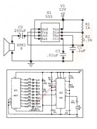
An astable oscillator is constructed using a 555 timer, producing an alarm tone of 1.8 kHz that directly drives a speaker. This fundamental alarm circuit serves as a basis for various other projects in the book. Although the circuit...