
Discrete components sound and light control stairs delay switch circuit 5

The circuit operates using a combination of photoresistive and acoustic sensing elements to control the lighting system effectively. The photosensitive resistor (R1) detects ambient light levels, influencing the operation of the transistors (VT2 and VT3). When the ambient light is low, R1 exhibits low resistance, allowing VT2 to conduct and keeping VT3 in a non-conductive state, thus preventing the lamp (E) from illuminating. Conversely, when ambient light increases, R1's resistance rises, leading to the deactivation of VT2, which enables VT3 to power the lamp.
The acoustic detection mechanism is facilitated by the transistor VT1, which is triggered by sound waves, such as clapping. This sound is coupled to VT1, activating it and allowing current to flow, which energizes the circuit and turns on the lamp. The capacitor (C) plays a crucial role in maintaining the conduction state of VT1 momentarily after the sound has ceased. This feature ensures that the light remains on for a brief delay, enhancing user convenience.
The design includes a trim resistor (R) that allows for the adjustment of the sensitivity of the voice activation feature. By modifying the resistance, the user can either increase or decrease the sensitivity, tailoring the circuit's responsiveness to ambient noise levels. This adjustment is particularly useful in environments with varying noise conditions.
In summary, the circuit provides a practical solution for stairway lighting with both light and sound activation features. It combines photoresistive and acoustic sensing technologies, offering flexibility in sensitivity adjustment and ensuring reliable operation in various lighting and sound conditions.A relatively simple circuit Lu Qing, stair walkway light control delay light switch, the disadvantage voice a little less sensitive, and sometimes difficult general conversatio n Lu canthus trigger, but you can beat the sound of shoulder F switch or direct slap open close open panel beam light. Photosensitive resistance Rl., R, and the composition of VT2 light control lb Road, H days, RI. Showed a low resistance, VT2 conduction, VT3 door is clamped at a low level, VT3 off, lamp E does not shine.
At this time (jl by VDa, marrow grams electrically to 13 (iV about (vs LED light tube voltage value plus positive l sentence drop) evening RI. Showed a high resistance, VT Off, VT3 lifting of the blockade, but because R ,. i far Ding R, VT3 is still in the off state, the light is still on, when someone from the sound of speech or clap clap, Ij pick up acoustic signals through (coupled, direct-cho trigger VT1 open.
Sh, then 1: ~. power by about 6V iF VD6, VT1 VT3 f J Feng people pole, so VT3 trigger the opening of electric powered lights E-emitting. VT1 lose after the sound f J pole} U flow, but the mountains in C, stored charge through R. to put VT1 in, make VT1 work under sunny Xi iu claw stop, so VT1 still maintain open state (j. Hui: discharge at the same time, but also by VDj, R, full-wave pulsating DC charging but R; a big R, Therefore (1 voltage across gradually drop, Sheng finally unable to maintain VT1 conduction.
seasonal ferry pulsating DC zero crossing, VT1 off. In this case C. continue VDo, R, and VT3 gate charge, the charging current can be maintained VT3 conduction state remains until full charge to f, V [3 seeker trigger current when the AC zero crossing that is shut off, turn off the lamp E. arc tube I.EI) in this collapse was two: one foot at night emitting low light, indicating the switch position bone; the second is isolated from the action, so that the anode and VT3 VT] usually work in the whole gate crossing the pulsating DC voltage conditions F.
trim resistor. RI side of town for the festival circuit voice sensitivity increase Save resistor R. the resistance can be adjusted from the control light control circuit point; after this circuit is energized, if not out long bright lights F can be increased R. (or decrease wind) adjustment.
Related Circuits
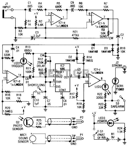
Sound or light sensors connected to J2 produce a voltage that is amplified by IC1-a and IC1-b. A positive trigger voltage developed by D1 and R3, and amplified by IC1-d, drives IC2 and IC1 to trigger SCR1. SCR1 is...
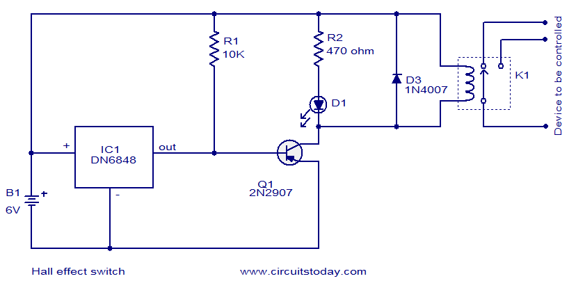
The circuit diagram presented is for a Hall Effect switch. The core component of this circuit is the Hall Effect sensor IC DN6848 from Panasonic. This integrated circuit features a Hall Effect sensor, a Schmitt trigger circuit, a power...
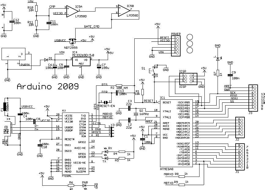
Research has been conducted on a project aimed at enhancing understanding of electronics, networking, and programming. The project involves the construction of an online thermometer suitable for applications requiring temperature monitoring. The current work environment is a laboratory where...
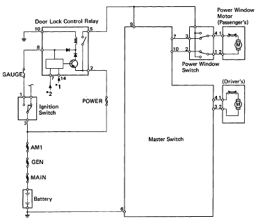
The following circuit illustrates the 1993 Toyota Hilux Pickup Power Window Control System Electrical Circuit Diagram. It is beneficial for both personal use and for mechanics during repairs. Key components include the door lock relay, junction block, power window...
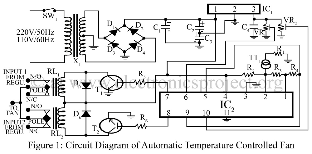
An automatic temperature-controlled fan regulates the fan speed based on temperature variations using the temperature transducer AD590 and an op-amp LM324 circuit diagram. The automatic temperature-controlled fan circuit utilizes the AD590 temperature transducer, which provides an output voltage that is...
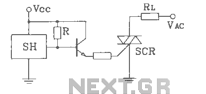
SH Hall opened with a double silicon output interface circuit The SH Hall sensor circuit is designed to provide a dual silicon output interface, which enables enhanced signal processing capabilities. This circuit typically integrates a Hall effect sensor that detects...