
Electronic Diagram Mixer Audio

The Audio Mixer circuit operates by combining multiple audio signals into a single output. The core of this design is based on bipolar junction transistors (BJTs) or field-effect transistors (FETs), which serve as the primary amplifying elements. The input audio signals are fed into the base (or gate) of the transistors, where they are mixed and amplified.
The circuit typically includes several input channels, each with its own gain control to adjust the level of each audio source before mixing. A resistor-capacitor (RC) network may be employed for each channel to filter out unwanted frequencies, ensuring that only the desired audio signals are processed. The outputs from each transistor are then combined at a common node, which leads to the output stage.
To enhance performance and protect the circuit from potential over-voltage or current surges, a protective reactor is integrated into the design. This reactor, with a tolerance of 1%, helps to stabilize the circuit by smoothing out fluctuations in the power supply and preventing distortion in the audio output.
In summary, this simple transistor-based audio mixer circuit provides an accessible solution for mixing audio signals, making it suitable for various applications in audio processing and sound reinforcement systems. Its straightforward design and the use of common components make it an excellent choice for both hobbyists and professionals looking to implement basic audio mixing functionality.This scheme named Audio Mixer a real very simple and component easy to be got, generally circuit Audio Mixer is used with a few IC, but at this Audio Mixer circuit only requires transistor as its brace. For good result applied preventive reactor with tolerance 1%. 🔗 External reference
Related Circuits
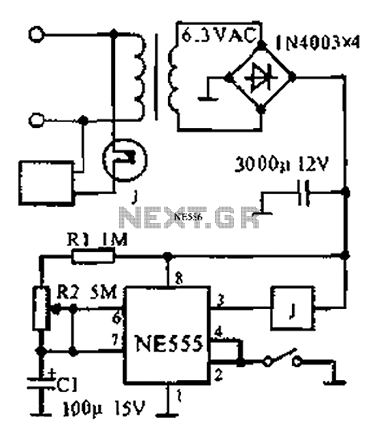
The provided information indicates that when the power supply operates between 0 to 1 hour, an AC circuit diagram is established using a 555 timer configured as a one-hour timer. The relay utilized is a J 212 IRC MR312C...

The circuit consists of two main sections: a charger power supply and an LED driver. The charger power supply is designed using a 3-terminal adjustable regulator (IC1) LM317, while the LED driver is based on a BD140 transistor (T2)....
Approximately one watt RMS appears to be a suitable output level, which is also the maximum power that a basic amplifier powered by 12V can deliver to an 8 Ohm speaker. A very low saturation amplifier may reach up...
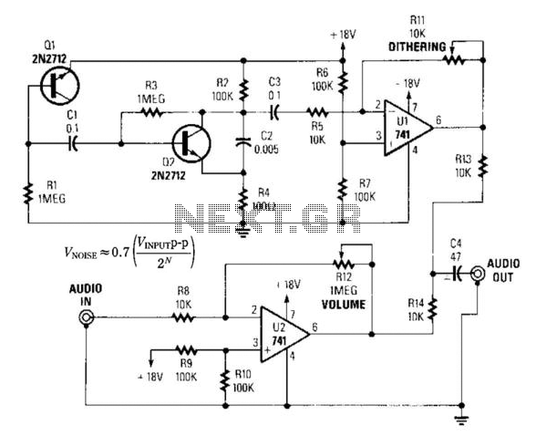
By introducing a small amount of noise to a signal intended for digitization (approximately 0.7 bits), where n represents the number of bits, for instance, an 8-bit signal with a peak-to-peak voltage of 2 V would result in a...
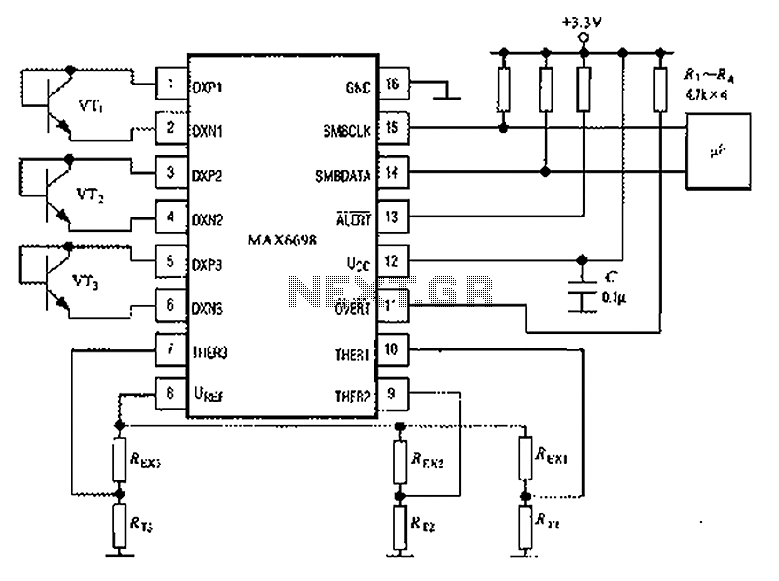
The circuit illustrated in the figure involves the MAX6698 maximum temperature sensor, which utilizes three transistors (VT1 to VT3) and three thermistors (RT1 to RT3). An internal reference voltage source is connected through resistors UREF REX1 to REX3, providing...
The double-ended working core square wave inverter transformer area product formula Bm represents the maximum magnetic flux. The primary side of the transformer features switches S1 and S2 in parallel with IRF32055. This parallel configuration is primarily due to...