
Audio Ditherizing Circuit For Digital Audio Use

The described circuit operates by injecting a controlled amount of noise into the input signal to enhance the digitization process. The purpose of adding noise is to mitigate quantization errors that can occur during the analog-to-digital conversion, especially in low-level signals. The transistor Q1 serves as a noise generator, producing a random noise voltage that is then amplified by the operational amplifier U1 through transistor Q2, which aids in maintaining the integrity of the noise signal.
Resistor R11 plays a crucial role in determining the amplitude of the noise injected into the signal. By adjusting the value of R11, the designer can fine-tune the level of noise to achieve optimal performance based on the specific characteristics of the signal being processed. Meanwhile, resistor R12 is essential for controlling the gain of the amplifier circuit, allowing for adjustments to ensure that the noise level is appropriate for the digitization process without overwhelming the original signal.
The overall configuration of the circuit must be carefully designed to ensure stability and reliability. Proper biasing of the transistors and selection of component values are critical to achieving the desired noise characteristics and gain. Additionally, considerations regarding power supply decoupling and layout can significantly influence the performance of the circuit, ensuring that the noise introduced is consistent and predictable. This design approach is particularly beneficial in applications where high precision in signal conversion is required, such as in data acquisition systems, audio processing, and communication systems. By adding a small amount of noise to a signal to be digitized (about 0.7 bit): where: n = # of bits. For example, 8 bits and 2 V p-p would be 0.0055 V. This circuit uses a transistor (Ql) and an amplifier (Q2 and Ul) to generate the noise signal. Rll controls the noise injection and R12 controls the gain of the system.
Related Circuits
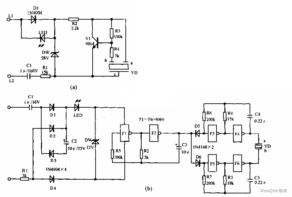
The telephone electronic ringer circuit is illustrated in the provided figure. It features an NPN transistor (either 9014 or 3DG12) as the primary component. The sound device, referred to as YD, functions as both a feedback device and is...
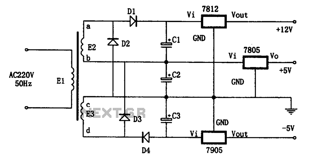
The circuit illustrated in the figure represents a specialized power supply configuration. It is straightforward in design and can be constructed using two identical secondary windings to generate three distinct DC voltage outputs: +5V, -5V, and +12V. The circuit...
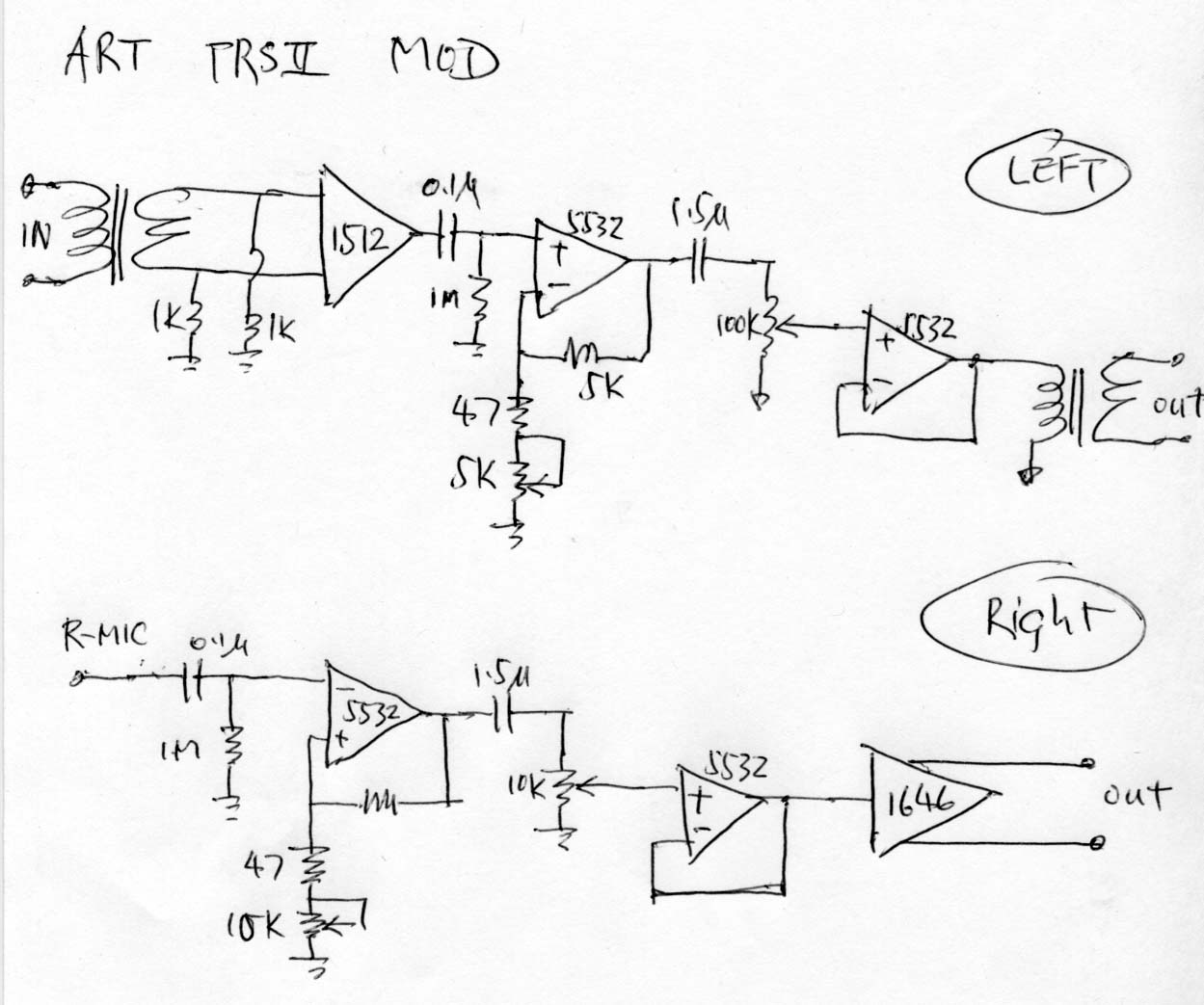
The ART TPS2 is a starved tube microphone preamplifier that utilizes a single 12AX7 tube operating at approximately 50V plate voltage to enhance the sound quality. Initially, the intention was to construct an entirely solid-state preamp, leading to the...
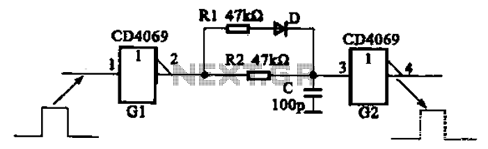
The inverter circuit using CD4069 is configured with a delay and width adjustment. When the output of the inverter (G1) is high, the capacitor (C) charges through resistor (R1) and diode (D). The voltage across capacitor C quickly reaches...

The digital circuit that is particularly useful is the One-Shot circuit, also known as a monostable multivibrator circuit. This circuit exhibits a specific behavior where it generates a single output pulse in response to an input trigger. The One-Shot circuit,...
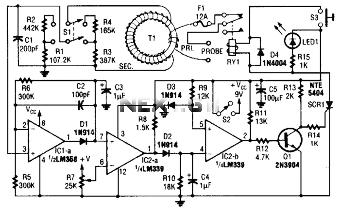
This circuit is an adjustable electronic circuit breaker that features a toroidal transformer designed to sense a 60-Hz load current. The transformer, labeled as T1, has a two-turn winding for the primary side and 100 turns of #30 gauge...