
Electronic Dice

The circuit design effectively simulates a dice roll using basic electronic components. The IC555 is configured in astable mode, generating a continuous square wave that serves as a clock signal for the CD4017. The frequency of the clock is adjustable through R1 and C1, allowing for customization of the speed at which the LEDs cycle. The CD4017's output pins are connected to the LEDs, which are typically arranged in a visually appealing manner on the enclosure.
When S1 is activated, the clock signal enables the CD4017 to sequentially activate the outputs corresponding to the LEDs. The reset function, achieved by connecting pin 5 to pin 15, ensures that the counter only counts to 6, aligning with the six faces of a standard die. The random selection of an LED upon releasing the switch is a result of the latching mechanism, which maintains the last activated output until the next press of S1.
This circuit not only serves as a fun electronic project but also provides a practical application of digital counting and LED control, making it an excellent educational tool for understanding basic electronics and digital logic. Proper assembly and labeling enhance usability, ensuring that users can easily interpret the output as a dice roll.It is good idea to put this circuit in a box and mark/write each LED with number 1 to 6. Now, when switch S1 is pushed momentarily, any one of the 6 LEDs will glow. The Number marked for glowing LED becomes dice`s output. Every time S1 is released, new LED will glow randomly. Chances for each LED to glow is 16. 66%. This circuit makes use of two IC s, IC555 and IC-CD4017. IC-555 is used as square wave generator, and IC(CD4017) as a counter. Actually CD4017 is a divide-by-10 johnson-counter with 10 decoded outputs. IC555 simply generates clock for CD4017, and the clock frequency is controlled by R1 and C1. Counter CD4017 starts counting from 0 to 9 by putting high voltage on each of the 10 pins (one after another). The High voltage shifts from one pin to another on every positive edge of the clock. Since, in our circuit pin-5 is shorted with pin-15(reset), the counter gets reset after reaching 6, and again starts from 0.
Now, when S1 is pushed, IC555 generates clock for CD4017. This clock enables CD4017 to count from 0 to 6 by putting high voltage on each of the 6 pins (one after another). These 6 pins are connected to 6 respective LEDs. When S1 is released, high voltage gets latched to any one of the 6 pins, and this becomes output of the DICE.
All the material on this website is copyright property of Material on this site is for personal use only and can not be used for any commercial activity without written permission of Use the information provided within this website at your own risk. Information within this website is provided as-is without warranty or guarantee of any kind. Please read Copyright and Disclaimer notice carefully. 🔗 External reference
Related Circuits
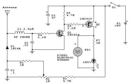
This electronic RF detector project is designed using common transistors and a few standard electronic components. The RF detector responds to RF signals below the standard broadcast band and well over 500 MHz, providing both visual and audible indications...
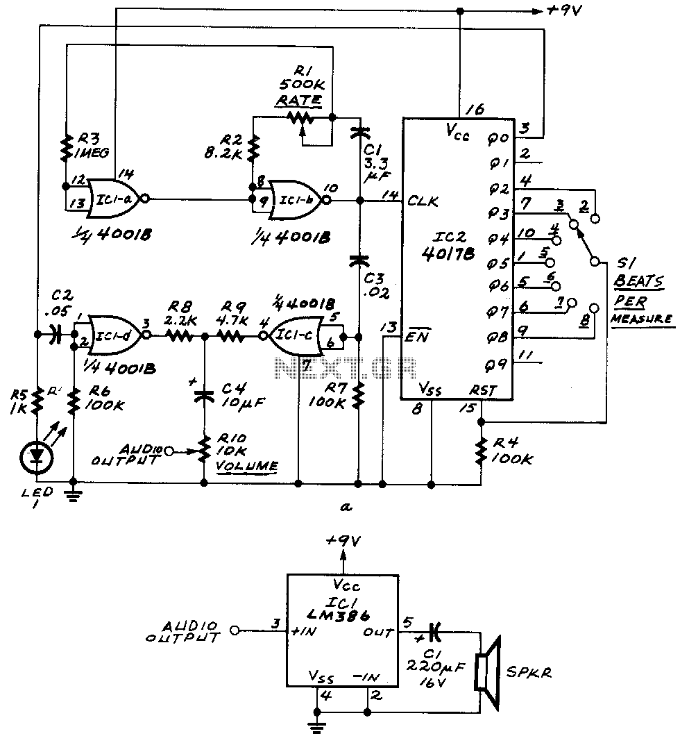
ICla and IClb form an astable multivibrator. The astable's signal is fed to IC1c, as well as to the clock input of IC2, a 4017B decade counter. The outputs Q0 through Q9 of that IC become high one at...
This circuit utilizes a synthesized sound chip from Holtek, the HT-2811, which produces the sound of a "ding-dong" chiming doorbell. Additionally, it incorporates a CMOS 4026 counter display driver integrated circuit (IC) to tally the number of visitors. The...
The power supply has been simplified. Power transformers and rectifiers have been omitted, and some components from the MOSFET voltage regulator circuits have been removed, including 1N5242 zener diodes between the source and gate and 10k resistors in series...
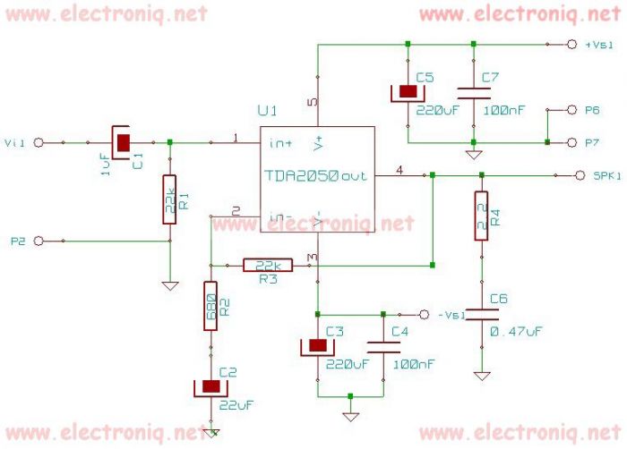
The TDA2050 integrated circuit can be used to design a simple high-fidelity audio power amplifier, intended for use as a Class AB audio amplifier. Due to its high power capabilities, the TDA2050 audio power amplifier can deliver up to...
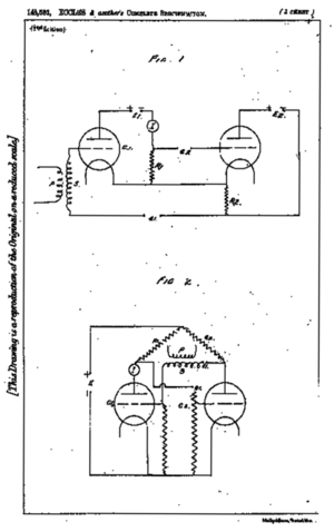
A flip-flop is a bistable multivibrator. It is a circuit that has two output states and is switched from one to the other by means of input signals. A flip-flop serves as a fundamental building block in digital electronics, primarily...